
Exposure apparatus and device manufacturing method

a technology of equipment and manufacturing method, applied in the field of equipment, can solve the problems of reducing the efficiency of the process, affecting the quality of the product, so as to reduce the alignment error or the focus error

Active Publication Date: 2011-05-05
CANON KK
View PDF5 Cites 8 Cited by
  • Summary
  • Abstract
  • Description
  • Claims
  • Application Information

AI Technical Summary

Benefits of technology

[0007]The present invention provides an exposure apparatus which attains a target pattern shape and line width by reducing an alignment error or a focus error.

Problems solved by technology

However, this color resist is hindered from bringing about the polymerization reaction because its pigment components easily absorb the exposure light, and the radicals produced by it are trapped by oxygen in the air.
However, this method may generate defects because the oxygen barrier film has poor wettability on the resist, and requires a higher cost related to an additional process of coating a resist with an oxygen barrier film.
Furthermore, in the method of providing an oxygen barrier film, the oxygen concentration cannot be controlled, and this lowers the flexibility for finer pattern shape / dimensional precision control in forming a fine pattern.
However, a performance problem is posed when the inert gas is always blown onto the resist to purge it.
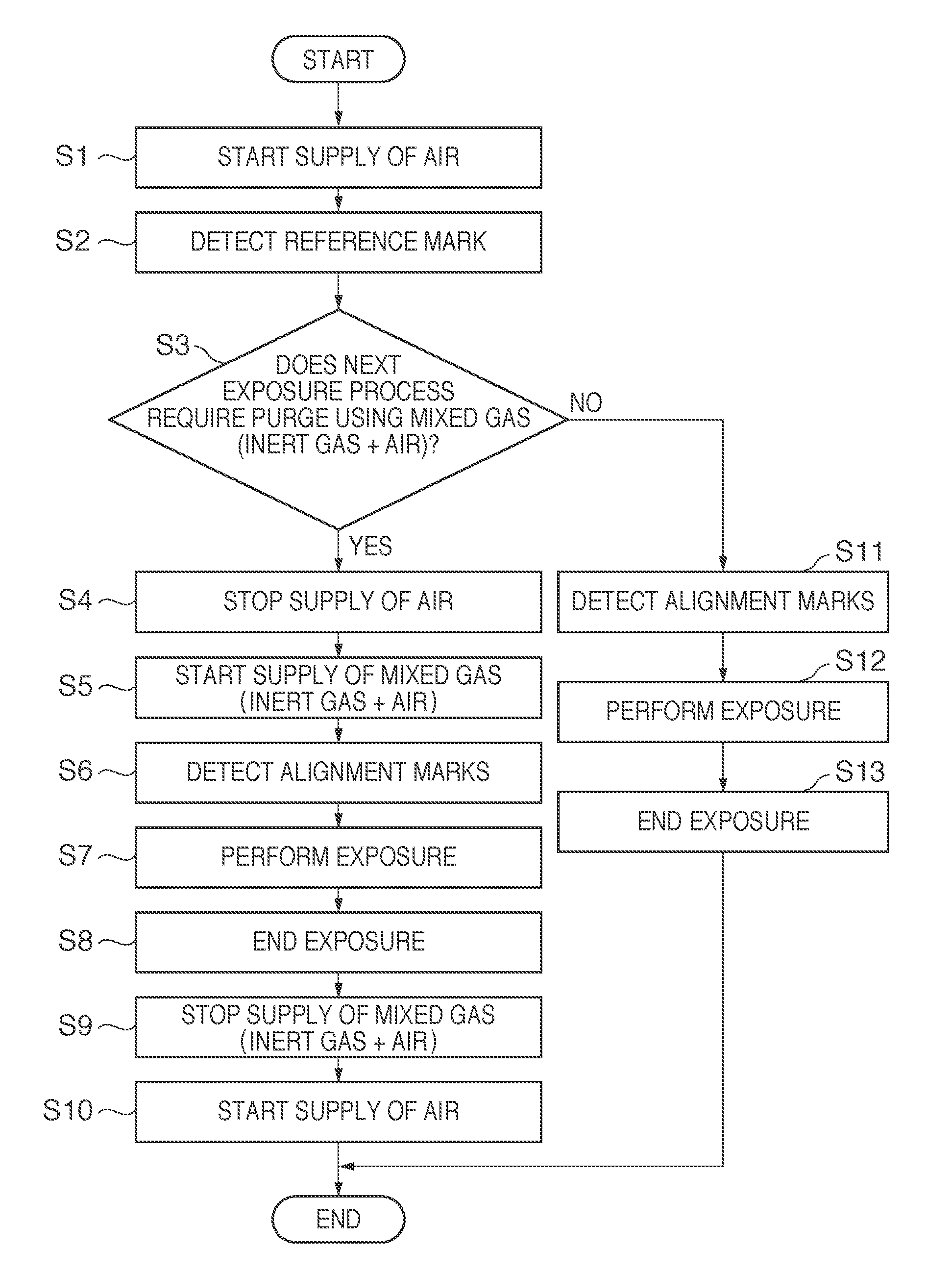
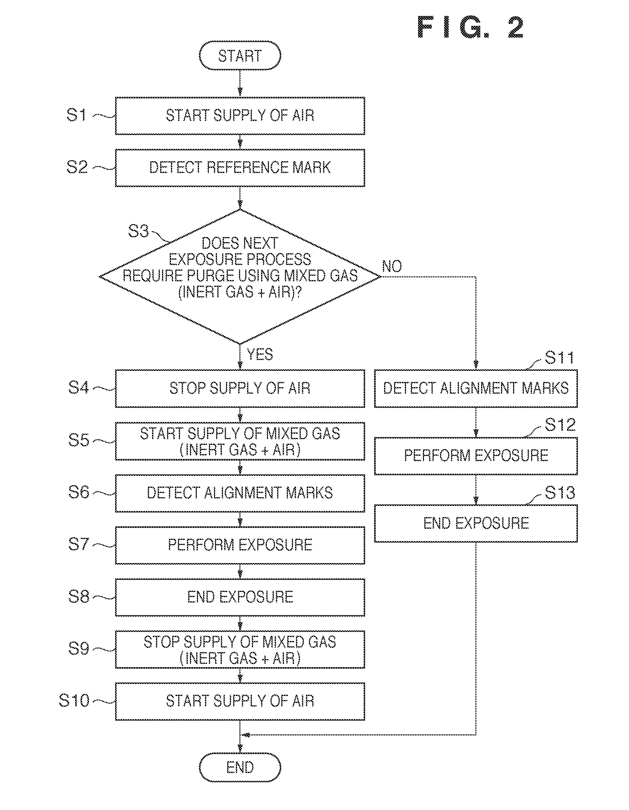
Therefore, when the reference mark is detected while flowing an inert gas onto the resist, a detection error occurs in response to a change in refractive index due to factors associated with the inert gas.

Method used


Image

  • Exposure apparatus and device manufacturing method
  • Exposure apparatus and device manufacturing method
  • Exposure apparatus and device manufacturing method

Examples


Embodiment Construction

Exposure Apparatus

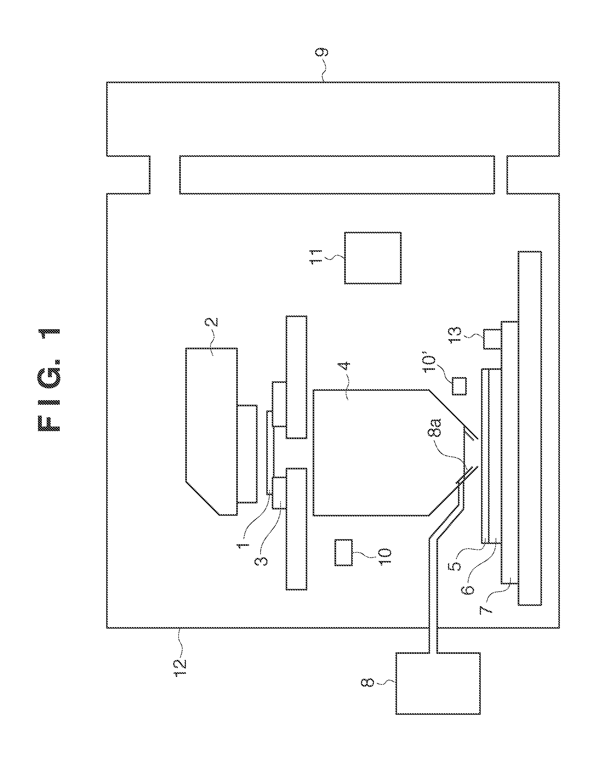
[0012]FIG. 1 is a view showing the arrangement of an exposure apparatus, which exposes a resist 5 while driving a substrate stage 7 in accordance with a recipe, according to the present invention. Light emitted by a light source such as a mercury lamp, an ArF excimer laser, or a KrF excimer laser passes through an illumination system 2, and irradiates a reticle 1, thereby transferring the pattern on the reticle 1 onto the resist 5, formed on a substrate 6, via a projection optical system 4. The reticle 1 is movably held by a reticle stage 3, and the substrate 6 is movably held by the substrate stage 7. A reference mark 13 for calibration is formed on the edge of the substrate stage 7. The exposure apparatus is disposed in an exposure chamber 12, and the space in the exposure chamber 12 is maintained in an air atmosphere whose temperature and humidity are controlled by an atmosphere maintaining unit 9. Air or a mixed gas containing air and an inert gas is supplied f...


PUM


Abstract

An exposure apparatus includes an atmosphere maintaining unit which maintains an exposure chamber in an air atmosphere, a gas supply unit which supplies air or a mixed gas containing air and an inert gas to a local space, between a final surface of a projection optical system and a substrate, a detector which detects an alignment mark and a reference mark formed on the substrate stage, and a controller. The controller controls the gas supply unit not to supply the mixed gas to the local space when the detector detects the reference mark, and controls the gas supply unit to supply the mixed gas to the local space when an instruction to detect the alignment mark upon setting the local space in a mixed gas atmosphere, and expose the substrate based on the detection results of the reference mark and the alignment mark is issued from the recipe.

Description

BACKGROUND OF THE INVENTION[0001]1. Field of the Invention[0002]The present invention relates to an exposure apparatus and a method of manufacturing a device such as a color filter or a liquid crystal display device using the exposure apparatus.[0003]2. Description of the Related Art[0004]A variety of methods of manufacturing color filters have been developed, and include, for example, staining methods, printing methods, electrodeposition and electrolytic methods, and pigment dispersing methods. Among such of methods, the pigment dispersing methods are the current mainstream from the viewpoint that they are stable and easy manufacture. A method of using a photosensitive acrylic polymer as a typical pigment dispersing method forms a pattern on a color resist, which contains an acryloid photosensitive resin and has both a coloring function and a photosensitizing function, using a photolithography technique. This color resist is a negative resist, and produces radicals, which contribut...

Claims


Application Information

Patent Timeline
Patent Type & Authority Applications(United States)
IPC IPC(8): G03B27/42
CPCG03B27/42G03F9/7096G03F7/70933G03F9/7088G03F7/70341
Inventor TAKAGI, ATSUSHIMURAGUCHI, YOYAFUNAYOSHI, TOMOMI
Owner CANON KK
Learn More