Adaptive-gain step-up/down switched-capacitor DC/DC converters

Inactive Publication Date: 2011-05-05
THE ARIZONA BOARD OF REGENTS ON BEHALF OF THE UNIV OF ARIZONA
View PDF7 Cites 58 Cited by
  • Summary
  • Abstract
  • Description
  • Claims
  • Application Information

AI Technical Summary

Benefits of technology

[0015]To achieve the above and other objects, the present invention is directed to a power stage for a switched capacitor (SC) DC-DC converter comprising a number of capacitors, power switches and a controller. It can be flexibly configured to supply both step-up and step-down voltages from a power source. Unlike a traditional SC power stage, this invention uses switch and capacitor reconfiguration with interleaving regulation to reduce input noise, output ripple and improve loop-gain bandwidth.
[0032]The power stage presented in that reference consists of three capacitors and fifteen switches to achieve the seven GRs (gain ratios). They operate in two phases: the charge phase where all the capacitors get charged from the input and the discharge phase where all the capacitors get discharged at the output. These converters have large input noise as the voltage across the capacitors changes suddenly and large ripple voltage at the output as no capacitor provides charge at the output during the charge phase. To improve the performance, two such converters can be placed in parallel and operated in an interleaving manner so that there is continuous charging at the input and discharging at the output. This greatly reduces the input noise and output voltage ripple. However, this would also mean doubling the number of capacitors (6) and switches (30). In at least some embodiments, the invention proposed here achieves this performance with only three capacitors and eighteen switches using the three phase cyclic charge transference. In this mechanism, the switches are turned on / off in a way so that at least one capacitor gets charged by the input and one capacitor gets discharged at the output during each phase. The other capacitor is used either to provide certain GR or if not needed, it gets charged from the input as well. The capacitors exchange the positions in the next phase. The process repeats one more time after which the capacitors are back at their initial position. This way, after a full three phase clock period, each capacitor is at least charged once by the input and discharged once at the output. This continuous charging and discharging renders the benefits of the interleaving operation with a reduced number of capacitors and switches.

Problems solved by technology

Conventional switching converters provide high power efficiency, but suffer from severe electromagnetic interference (EMI) noise and bulky system profile, due to the employment of inductive components.
The difficulty of implementing step-down SC converters lies in the fact that it is much harder to maintain high efficiency than in their step-up counterparts.
A linear regulator does not suffice under this scenario when the dropout voltage is large between the output and the input, due to the inherently poor efficiency.
However, as low power operation gets ever more critical in VLSI systems, step-down voltage conversions are in high demand.
This results in a sudden inrush of current generated in the input power line and propagated into the capacitor.
Sudden increase in current creates voltage spikes across the wire which is then coupled into the power source, leading to large switching noise.
If the same power source is used by other parts of the system, this input noise gets coupled to those parts as well.
This affects the transient response and leads to large variation and noise at the regulated power line.
This current ripple causes substantial switching noise, which will then be coupled into the entire IC chip, through the power supply metal lines and the substrates of power transistors.
Although the prior art can provide multiple GRs, the known power converters suffer from large inrush input current, high output ripples and slow transient response.
The separation of the charge and discharge actions leads to large current and voltage ripple problems as previous examples.
Techniques such as power stage are not applicable here, due to high number of required switches and capacitors.

Method used


Image

  • Adaptive-gain step-up/down switched-capacitor DC/DC converters
  • Adaptive-gain step-up/down switched-capacitor DC/DC converters
  • Adaptive-gain step-up/down switched-capacitor DC/DC converters

Examples


Embodiment Construction

[0056]A preferred embodiment will be set forth in detail with reference to the drawings, in which like reference numerals refer to like elements throughout.

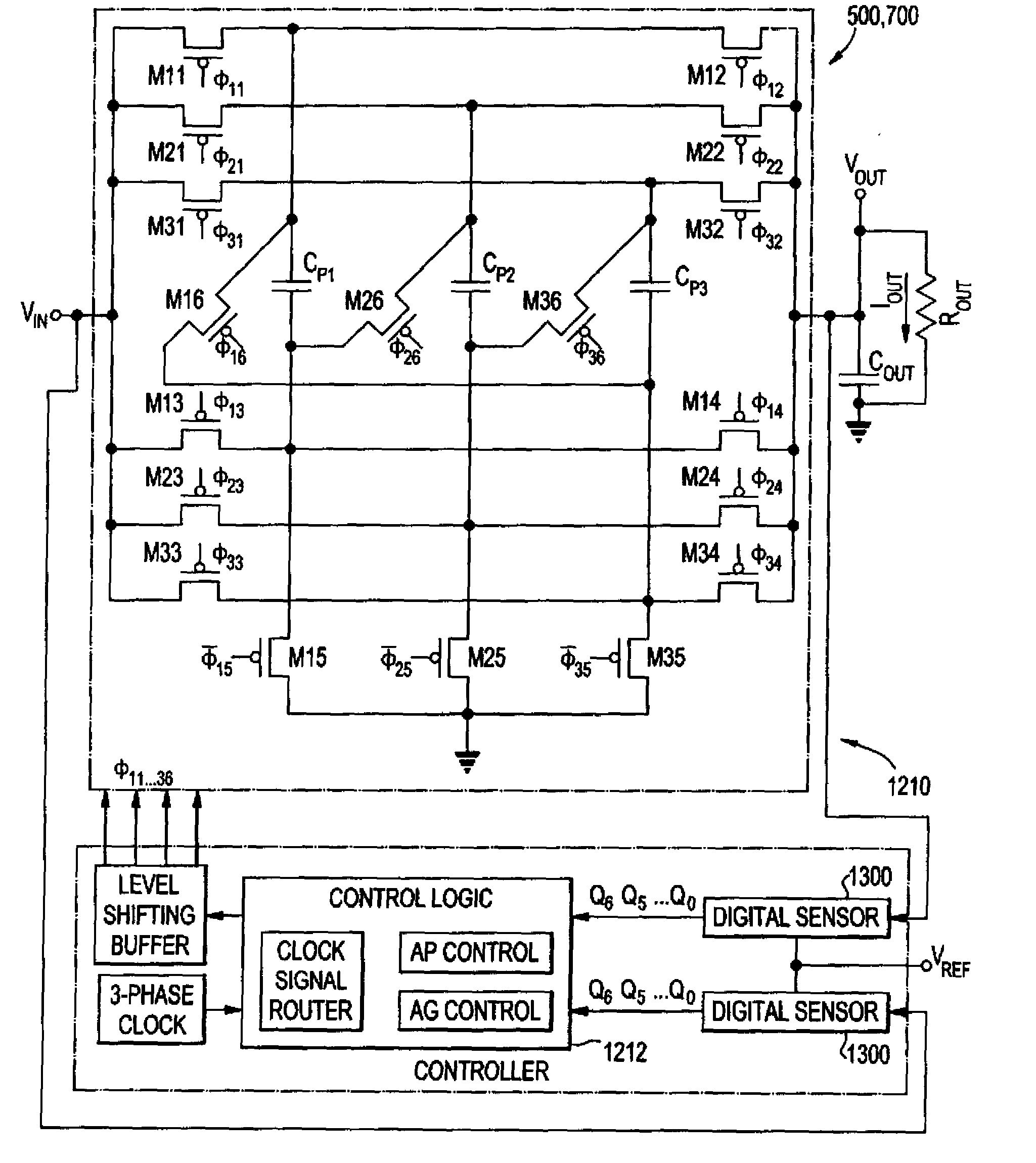
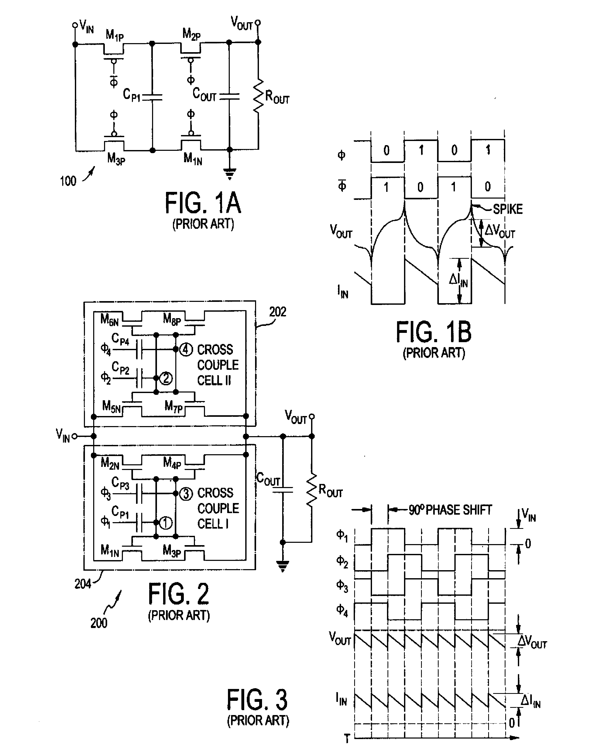
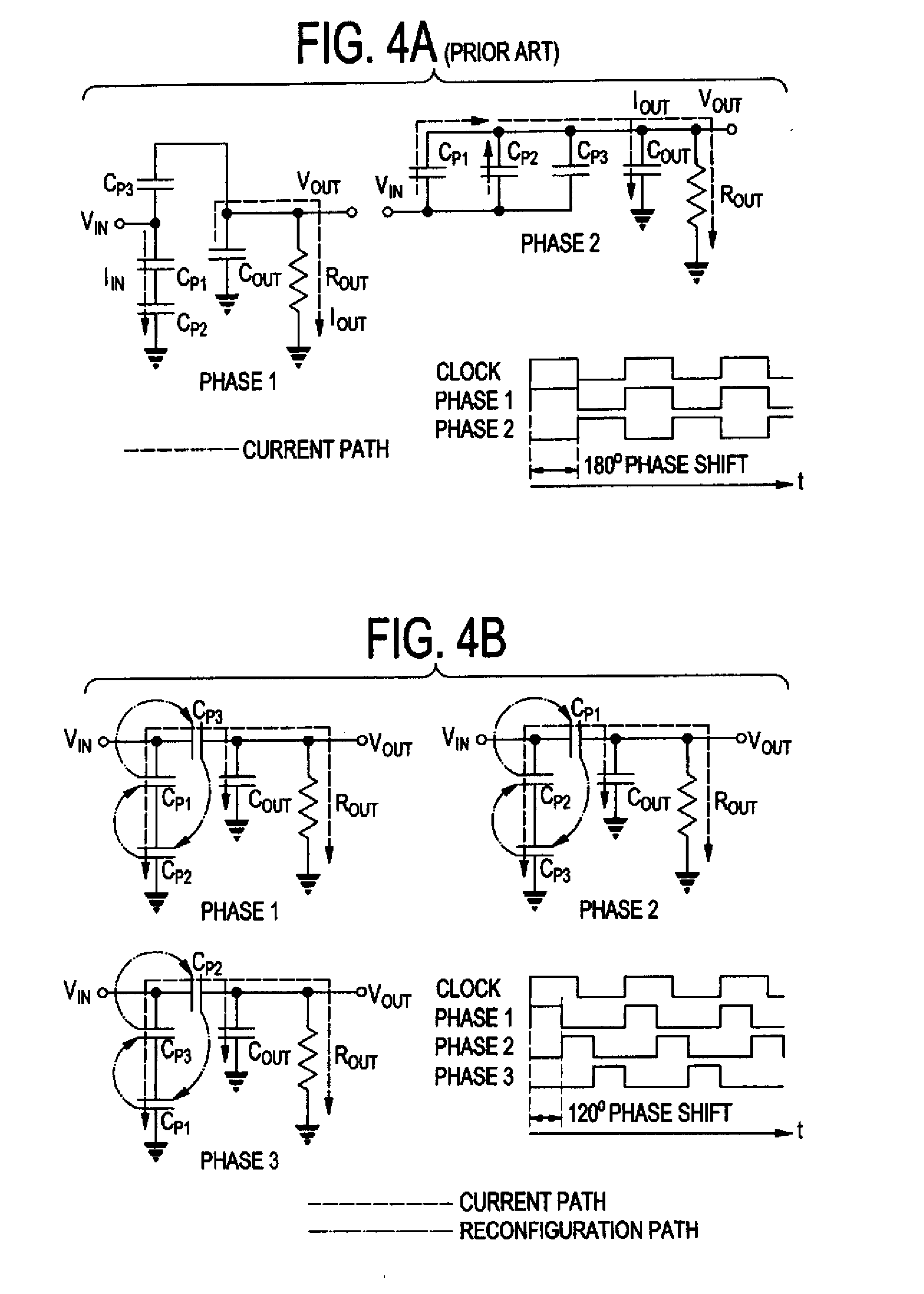
[0057]The preferred embodiment is directed to a new topology that provides the same advantage but using only half the switches. The preferred embodiment uses three capacitors and eighteen switches, although that number is illustrative rather than limiting. FIG. 5 shows the complete power stage 500. Using the on / off characteristics of a switch, the switch array can be configured to give six different gain states: 1 / 3, 1 / 2, 2 / 3, 1, 3 / 2, 2, and 3. The task is accomplished using a three-phase clock. The clock signals are routed according to the desired gain. The clock signals and capacitor configuration for all the gain settings are shown in FIGS. 6A and 6B, respectively. In each phase of the clock, at least one capacitor gets charged from the input, while one capacitor is discharged at the output. The other capacitor is used either ...


PUM


Abstract

A switched-capacitor DC-DC converter has a reconfigurable power stage with variable gain ratio and / or interleaving regulation for low ripple voltage, fast load transient operation, variable output voltage and high efficiency. Since the power stage has multiple switches per capacitor, the converter exploits reconfigurable characteristics of the power stage for fast dynamic control and adaptive pulse control for tight and efficient voltage regulation.

Description

REFERENCE TO RELATED APPLICATION[0001]The present application claims the benefit of U.S. Provisional Patent Application No. 61 / 004,095, filed Nov. 21, 2007, whose disclosure is hereby incorporated by reference in its entirety into the present disclosure.FIELD OF THE INVENTION[0002]The present invention is directed to DC / DC converters and more particularly to such converters using switches and capacitors in a reconfigurable manner.DESCRIPTION OF RELATED ART[0003]In recent years, multi-function portable devices have been proliferating over the electronic industry. The multiple functional modules in such a device are usually optimized at different power supply levels. To achieve a long battery runtime and low system profile, efficient and compact power conversion circuits become essential in these systems.[0004]Conventional switching converters provide high power efficiency, but suffer from severe electromagnetic interference (EMI) noise and bulky system profile, due to the employment ...

Claims


Application Information

Patent Timeline
IPC IPC(8): H02M3/07G05F1/46
CPCH02M3/07
Inventor MA, DONGSHENGCHOWDHURY, INSHAD
Owner THE ARIZONA BOARD OF REGENTS ON BEHALF OF THE UNIV OF ARIZONA
Why Eureka
Try Eureka