
System, apparatus, and method for modifying the order of memory accesses

a memory access and order technology, applied in the field of computer systems, can solve the problems of increasing the number of cores, and denying access to low priority requests for unacceptably long periods of tim

Active Publication Date: 2011-04-28
MICRON TECH INC
View PDF25 Cites 24 Cited by
  • Summary
  • Abstract
  • Description
  • Claims
  • Application Information

AI Technical Summary

Problems solved by technology

Such processing may be inefficient, resulting in a large number of page misses and conflicts, and thus requiring an extensive dedication of processor and / or memory controller resources to pre-charging and activating memory pages.
The problem with providing memory access strictly on priority, however, is that low priority requests may be denied access for unacceptably long periods of time.
One of the effects of the increase of the number of cores and threads will be requirements for greatly increased memory bandwidth, with a major side-effect that the address request stream seen by the memory system will be more random because of the increased number of actually independent or seemingly independent program execution sequences.
Increases in the size of level 1 and level 2 caches, which is how total memory bandwidth and latency issues have been addressed in the past by most system implementations, may be less effective and have less opportunity for growth because of the increased number of cores and limits on reasonable die size.
Furthermore, an increase in the number of threads being executed in each core will likely reduce average cache hit rates, again resulting in increasing memory traffic.
As DRAMs generally have multiple banks that can be cycled independently, this bank timing conflict wastes available memory bandwidth.

Method used


Image

  • System, apparatus, and method for modifying the order of memory accesses
  • System, apparatus, and method for modifying the order of memory accesses
  • System, apparatus, and method for modifying the order of memory accesses

Examples


Embodiment Construction

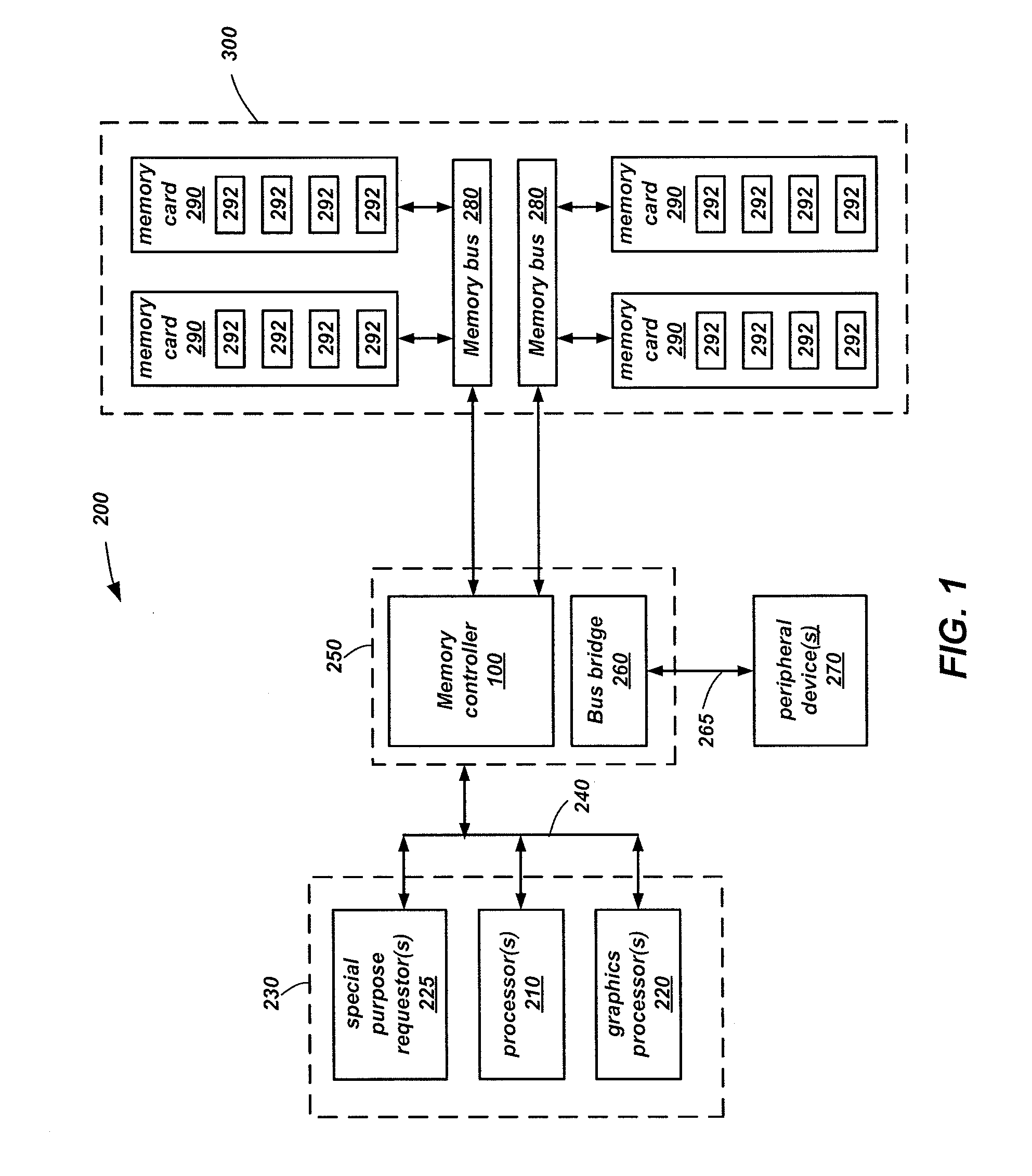
[0017]Embodiments disclosed herein include apparatuses and methods for generating improved memory performance in a system environment of multiple threads and multiple processors.

[0018]In the following detailed description, reference is made to the accompanying drawings which form a part hereof, and in which is shown by way of illustration specific embodiments in which the invention may be practiced. These embodiments are described in sufficient detail to enable those of ordinary skill in the art to practice the invention, and it is to be understood that other embodiments may be utilized, and that structural, logical, and electrical changes may be made within the scope of the present invention.

[0019]In this description, circuits and functions may be shown in block diagram form in order not to obscure the present invention in unnecessary detail. Furthermore, specific circuit implementations shown and described are only examples and should not be construed as the only way to implement ...


PUM


Abstract

Systems and methods for controlling memory access operations are disclosed. The system may include one or more requestors performing requests to memory devices. Within a memory controller, a request queue receives requests from a requestor, a bank decoder determines a destination bank, and the request is placed in an appropriate bank queue. An ordering unit determines if the current request can be reordered relative to the received order and generates a new memory cycle order based on the reordering determination. The reordering may be based on whether there are multiple requests to the same memory page, multiple reads, or multiple writes. A memory interface executes each memory request in the memory cycle order. A data buffer holds write data until it is written to the memory and read data until it is returned to the requestor. The data buffer also may hold memory words used in read-modify-write operations.

Description

CROSS-REFERENCE TO RELATED APPLICATION[0001]This application is a continuation of U.S. patent application Ser. No. 11 / 940,745, filed Nov. 15, 2007, pending, which will issue as U.S. Pat. No. 7,870,351 on Jan. 11, 2011, the disclosure of which is hereby incorporated herein in its entirety by this reference.TECHNICAL FIELD[0002]Embodiments relate to computer systems and, more particularly, to operational methods of memory controllers to increase memory access efficiency.BACKGROUND[0003]In most computer and data processing systems, the main active memory, which is typically random access memory (RAM), is a dynamic random access memory (DRAM). The structure of a DRAM is generally composed of a number of memory cells organized into banks. Each bank corresponds to an array of the memory cells with each cell being respectively associated with a digit of data (e.g., a bit) at a memory address. In particular, memory addresses within a bank are each designated by a row address and a column ad...

Claims


Application Information

Patent Timeline
Patent Type & Authority Applications(United States)
IPC IPC(8): G06F12/00
CPCG06F9/3004G06F9/30087G06F13/1673G06F13/1631G06F9/3834
Inventor RESNICK, DAVID R.
Owner MICRON TECH INC
Learn More