
Semiconductor device and method for manufacturing the same

a semiconductor and film transistor technology, applied in the field of thin film transistors, to achieve the effect of increasing the amount of on-current and field-effect mobility of a

Active Publication Date: 2011-04-14
SEMICON ENERGY LAB CO LTD
View PDF99 Cites 70 Cited by
  • Summary
  • Abstract
  • Description
  • Claims
  • Application Information

AI Technical Summary

Benefits of technology

[0006]An object of one embodiment of the present invention disclosed is to provide a thin film transistor having favorable electric characteristics and a semiconductor device including the thin film transistor as a switching element.
[0012]Because a region which is the closest to a source electrode and a drain electrode in an In—Ga—Zn—O-based oxide semiconductor film includes layers where the concentration of one or a plurality of indium, gallium, and zinc is higher than that in other regions (metal-rich layers), the metal-rich layers in the oxide semiconductor film have low resistance. In addition, the titanium oxide films (TiOx) formed between the source electrode and the oxide semiconductor film and between the drain electrode and the oxide semiconductor film have n-type conductivity. Therefore, with the above structure, contact resistance between the source electrode and the oxide semiconductor film and between the drain electrode and the oxide semiconductor film is reduced, and the amount of on-current and field effect mobility of the TFT can be increased.
[0020]Because a region which is the closest to a source electrode and the drain electrode in an oxide semiconductor film includes composite layers where the concentration of a metal is higher than that in other regions, and metal oxide films having n-type conductivity are formed between the source electrode and the oxide semiconductor film and between the drain electrode and the oxide semiconductor film, contact resistance between the source electrode and the oxide semiconductor film and between the drain electrode and the oxide semiconductor film is reduced, and the amount of on-current and field effect mobility of a TFT can be increased.

Problems solved by technology

Since there is limitation on manufacture of thin film transistors in terms of allowable temperature limit of a substrate, a transistor mainly used for a semiconductor display device is a thin film transistor including amorphous silicon that can be deposited at relatively low temperature, polysilicon that can be obtained by crystallization with use of laser light or a catalytic element, or the like in an active layer.

Method used


Image

  • Semiconductor device and method for manufacturing the same
  • Semiconductor device and method for manufacturing the same
  • Semiconductor device and method for manufacturing the same

Examples


embodiment 1

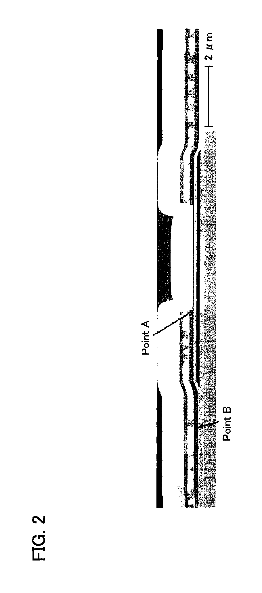
[0053]In this embodiment, described are results of computational science investigation on the phenomenon that a layer where the concentration of indium is higher than that in the other regions (an In-rich layer) and a titanium oxide film (TiOx) are formed in the vicinity of the interface between a metal film used as a source electrode or a drain electrode and an In—Ga—Zn—O-based oxide semiconductor film of a thin film transistor with a channel-etched structure using the In—Ga—Zn—O-based oxide semiconductor film as an active layer of the thin film transistor.

[0054]First, energy that is needed for formation of an oxygen-deficiency state (deficiency formation energy Edef) in respective case of indium oxide, gallium oxide, and zinc oxide, which are contained in an In—Ga—Zn—O-based oxide semiconductor, was calculated to investigate which metal oxide is likely to form the oxygen-deficiency state.

[0055]Note that the deficiency formation energy Edef is defined as Formula 1 below. A represen...

embodiment 2

[0079]In this embodiment, a structure of a thin film transistor which includes an oxide semiconductor film in a channel formation region is described by taking an example of a bottom-gate transistor with a channel-etched structure.

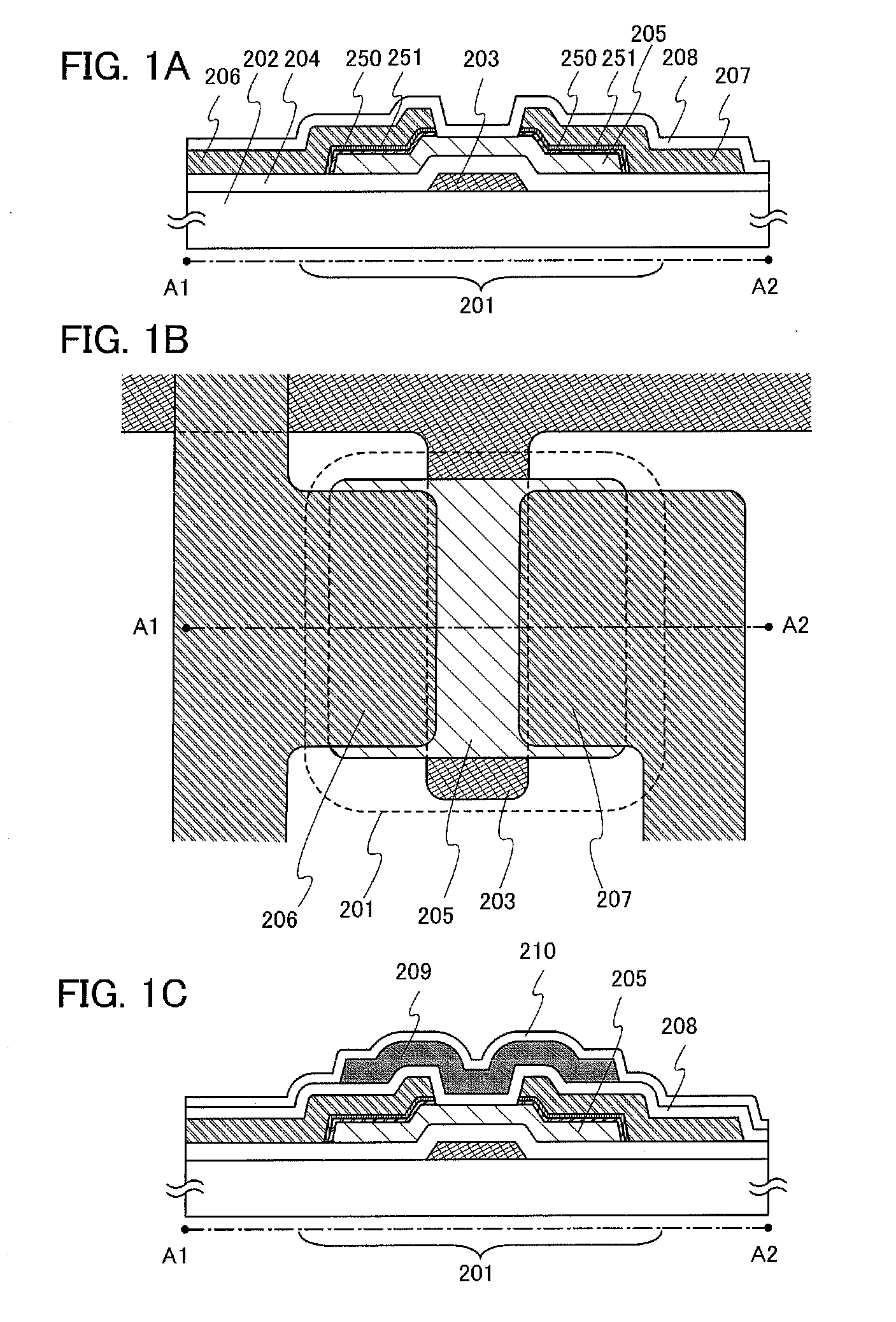
[0080]FIG. 1A illustrates a cross-sectional view of a thin film transistor 201 and FIG. 1B illustrates a top view of the thin film transistor 201 illustrated in FIG. 1A. Note that a cross-sectional view taken along dashed line A1-A2 in FIG. 1B corresponds to FIG. 1A.

[0081]The thin film transistor 201 includes a gate electrode 203 formed over a substrate 202 having an insulating surface, a gate insulating film 204 over the gate electrode 203, an oxide semiconductor film 205 which overlaps with the gate electrode 203 over the gate insulating film 204 and which includes composite layers 250 where the concentration of one or a plurality of metals contained in the oxide semiconductor is higher than that in other regions, a pair of metal oxide films 251 formed o...

embodiment 3

[0105]In this embodiment, a structure of a bottom-contact thin film transistor which is different from that of the thin film transistor 201 illustrated in Embodiment 2 is described. For the same portions as those in Embodiment 2 or portions having functions similar to those in Embodiment 2, Embodiment 2 can be referred to, and repetitive description thereof is omitted.

[0106]FIG. 12A illustrates a cross-sectional view of a thin film transistor 211, and FIG. 12B illustrates a top view of the thin film transistor 211 illustrated in FIG. 12A. Note that a cross-sectional view taken along dashed line B1-B2 in FIG. 12B corresponds to FIG. 12A.

[0107]The thin film transistor 211 includes a gate electrode 213 formed over a substrate 212 having an insulating surface, a gate insulating film 214 over the gate electrode 213, a source electrode 216 or a drain electrode 217 over the gate insulating film 214, metal oxide films 261 in contact with the source electrode 216 or the drain electrode 217, ...


PUM


Abstract

An object is to provide a thin film transistor having favorable electric characteristics and a semiconductor device including the thin film transistor as a switching element. The thin film transistor includes a gate electrode formed over an insulating surface, a gate insulating film over the gate electrode, an oxide semiconductor film which overlaps with the gate electrode over the gate insulating film and which includes a layer where the concentration of one or a plurality of metals contained in the oxide semiconductor is higher than that in other regions, a pair of metal oxide films formed over the oxide semiconductor film and in contact with the layer, and a source electrode and a drain electrode in contact with the metal oxide films. The metal oxide films are formed by oxidation of a metal contained in the source electrode and the drain electrode.

Description

TECHNICAL FIELD[0001]The present invention relates to a thin film transistor including an oxide semiconductor, a semiconductor device including the thin film transistor, and a method for manufacturing the semiconductor device.BACKGROUND ART[0002]A thin film transistor including a semiconductor film formed over an insulating surface is an essential semiconductor element for a semiconductor device. Since there is limitation on manufacture of thin film transistors in terms of allowable temperature limit of a substrate, a transistor mainly used for a semiconductor display device is a thin film transistor including amorphous silicon that can be deposited at relatively low temperature, polysilicon that can be obtained by crystallization with use of laser light or a catalytic element, or the like in an active layer.[0003]In recent years, a metal oxide having semiconductor characteristics which is referred to as an oxide semiconductor has attracted attention as a novel semiconductor materia...

Claims


Application Information

Patent Timeline
IPC IPC(8): H01L29/22H01L21/336H05B44/00
CPCH01L27/3262H01L27/1225H01L29/7869H01L29/45H10K59/1213H01L21/28211H01L21/324H01L29/06H01L27/1214H01L27/1222H01L29/78618H01L29/42384H01L29/4908
Inventor MIYANAGA, AKIHARUSAKATA, JUNICHIROSAKAKURA, MASAYUKITAKAHASHI, MASAHIROKISHIDA, HIDEYUKIYAMAZAKI, SHUNPEI
Owner SEMICON ENERGY LAB CO LTD
Learn More