Method of Manufacturing Magnetic Tunnel Junction Device and Apparatus for Manufacturing the Same

a technology of magnetic tunnel junction and manufacturing method, which is applied in the direction of nanoinformatics, magnetic bodies, instruments, etc., can solve the problems of reducing device performance and unable to obtain sufficient tunneling probability, and achieves excellent quality of manufactured products, high tmr ratio, and large ra product

Active Publication Date: 2011-04-07
CANON ANELVA CORP
View PDF14 Cites 9 Cited by
  • Summary
  • Abstract
  • Description
  • Claims
  • Application Information

AI Technical Summary

Benefits of technology

[0039]The present invention can form a MTJ device tunnel barrier controlled to have a uniform thickness and having the chemical uniformity including the stoichiometric composition between the ferromagnetic reference layer and the free layer.
[0040]The surface oxidation of the underlying ferromagnetic reference layer, which occurs during formation of a tunnel barrier, can be prevented or minimized.
[0041]This makes it possible to provide a MTJ device having a large R×A product and a high TMR ratio. In addition, there is also provided a MTJ device suitable for mass production, excellent in quality of manufactured products, and excellent in in-plane uniformity.

Problems solved by technology

Nonuniformity of the tunnel barrier in chemical composition and thickness greatly degrades the device performance.
However, since the Δ1 band in Fe is 100% spin-polarized at the Fermi level, a sufficient tunneling probability cannot be obtained in the antiparallel magnetization of the MTJ.

Method used


Image

  • Method of Manufacturing Magnetic Tunnel Junction Device and Apparatus for Manufacturing the Same
  • Method of Manufacturing Magnetic Tunnel Junction Device and Apparatus for Manufacturing the Same
  • Method of Manufacturing Magnetic Tunnel Junction Device and Apparatus for Manufacturing the Same

Examples


first embodiment

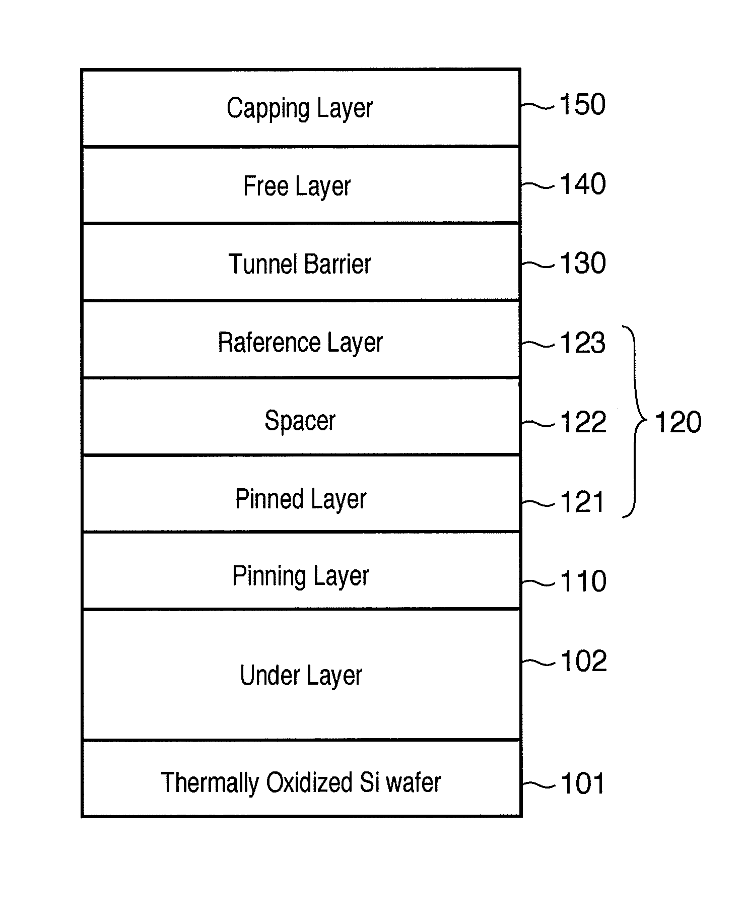
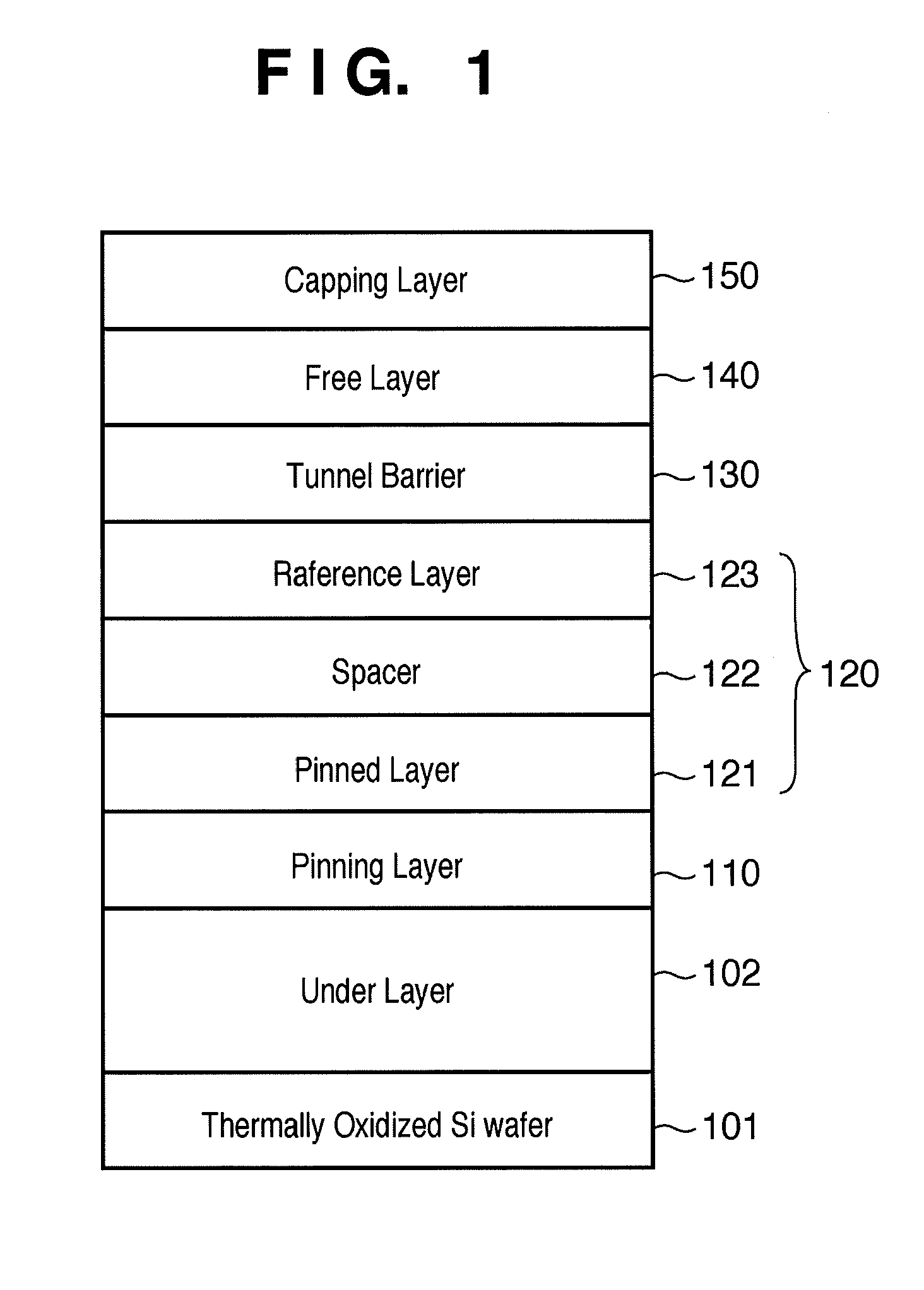
[0056]FIG. 1 shows a typical deposition structure of a tunnel resistance (TMR) sensor or memory element. A general MTJ includes a ferromagnetic pinning layer 110, synthetic antiferromagnetic pinned layer 120, tunnel barrier 130, and ferromagnetic free layer 140. In the deposition structure shown in FIG. 1, the synthetic antiferromagnetic pinned layer 120 includes a ferromagnetic pinned layer 121, nonmagnetic spacer 122, and ferromagnetic reference layer 123.

[0057]FIG. 9 exemplifies a MTJ device manufacturing apparatus and is a schematic plan view of a vacuum processing system for processing a magnetic tunnel junction device.

[0058]The vacuum processing system comprises a cluster type system having a plurality of deposition chambers 230, 240, and 250 capable of depositing thin films using the physical vapor deposition method. The plurality of deposition chambers 230, 240, and 250 are connected to a vacuum transport chamber 280 having robot loaders (not shown) at its center. Two load l...

second embodiment

[0089]The second embodiment will exemplify a MTJ tunnel barrier forming method of forming a tunnel barrier by inserting a very thin metallic Mg layer, forming an oxygen surfactant layer, performing radical oxidation at a low RF power, and depositing a metallic Mg cap layer.

[0090]As shown in FIG. 5B, an MgO barrier according to the present invention is formed as follows. A first metallic Mg layer 131 is deposited on a CoFeB ferromagnetic reference layer 123 to a two-atomic layer thickness (0.43 nm). The first metallic Mg layer is exposed to an oxygen atmosphere of 1.17×10⁻² Pa·sec (90 Langmuir) to form a first oxygen surfactant layer 132. A second metallic Mg layer 133′ is deposited on the first oxygen surfactant layer 132 to a two-atomic layer thickness (0.43 nm). The second metallic Mg layer 133′ is exposed to an oxygen atmosphere of 1.17×10⁻² Pa·sec (90 Langmuir) to form a second oxygen surfactant layer 135. A third metallic Mg layer 136 is deposited on the second oxygen surfactan...


PUM

PropertyMeasurementUnit
thicknessaaaaaaaaaa
temperatureaaaaaaaaaa
poweraaaaaaaaaa

Abstract

A method of manufacturing a magnetic tunnel junction device includes a barrier layer forming step of forming a tunnel barrier layer. The barrier layer forming step comprises a step of depositing a first metal layer, an oxygen surfactant layer forming step of forming an oxygen surfactant layer on the first metal layer, a step of deposing a second metal layer above the first oxygen surfactant layer, and an oxidation step of oxidizing the first metal layer and the second metal layer to form a metal oxide layer.

Description

TECHNICAL FIELD[0001]This application claims priority as a continuation application under 35 U.S.C. §120 to PCT / JP2009 / 053966, which was filed as an International Application on Mar. 3, 2009, designating the U.S., and which claims priority to Japanese Application 2008-052558, filed in Japan on Mar. 3, 2008. The entire contents of these applications are hereby incorporated by reference in their entireties.[0002]The present invention relates to a magnetic tunnel junction (MTJ) device and, more particularly, to a MTJ device applicable to a magnetic read head, magnetic random access memory (MRAM), and the like.BACKGROUND ART[0003]A magnetic tunnel junction (MTJ) device is basically a variable resistor including two ferromagnetic layers and a tunnel barrier sandwiched between them. The relative magnetization orientation of the two ferromagnetic layers causes electrons to pass through the tunnel barrier and make the spin-polarized electrons have different tunnel probabilities, thereby cha...

Claims


Application Information

Patent Timeline
Patent Type & Authority Applications(United States)
IPC IPC(8): H01L21/02C23C14/34
CPCB82Y10/00B82Y25/00B82Y40/00G11C11/16H01L43/12H01F10/3272H01F41/307H01L21/31683H01F10/3254G11C11/161H01L21/02175H01L21/02244H01L21/02252H10N50/01H01L21/02356
Inventor CHOI, YOUNG-SUK
Owner CANON ANELVA CORP
Why Eureka
Try Eureka