
Wireless transmission system, wireless communication device and wireless transmission method

Active Publication Date: 2011-03-31
SONY CORP
View PDF9 Cites 48 Cited by
  • Summary
  • Abstract
  • Description
  • Claims
  • Application Information

AI Technical Summary

Benefits of technology

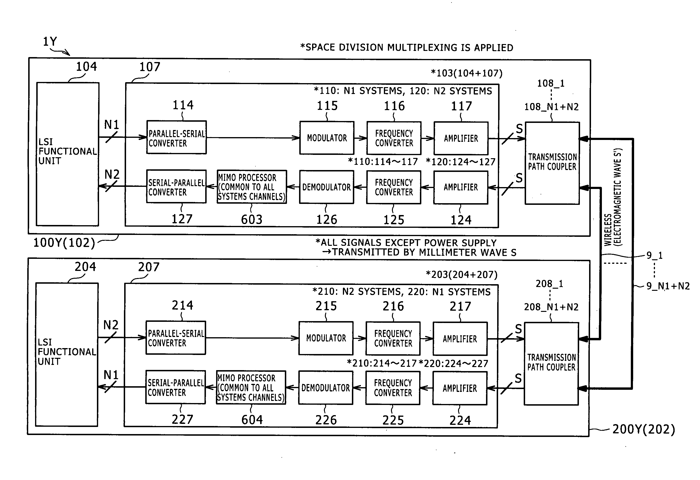
[0027]With the embodiment of the present invention, a mechanism suitable for wireless signal transmission between different apparatus or within an apparatus wherein the MIMO process is applied on the reception side is implemented without using the OFDM modulation method together. By applying the MIMO process to the reception side, the antenna distance can be reduced.
[0028]Since both of a desired wave and an unnecessary wave are handled as direct waves, it becomes possible to manage the path difference regarding the desired wave and the unnecessary wave and it becomes possible to determine the antenna arrangement so as to be convenient for the MIMO process on the reception side. As a result, in comparison with an alternative case wherein the present invention is not applied, the calculation scale of the MIMO process can be reduced.
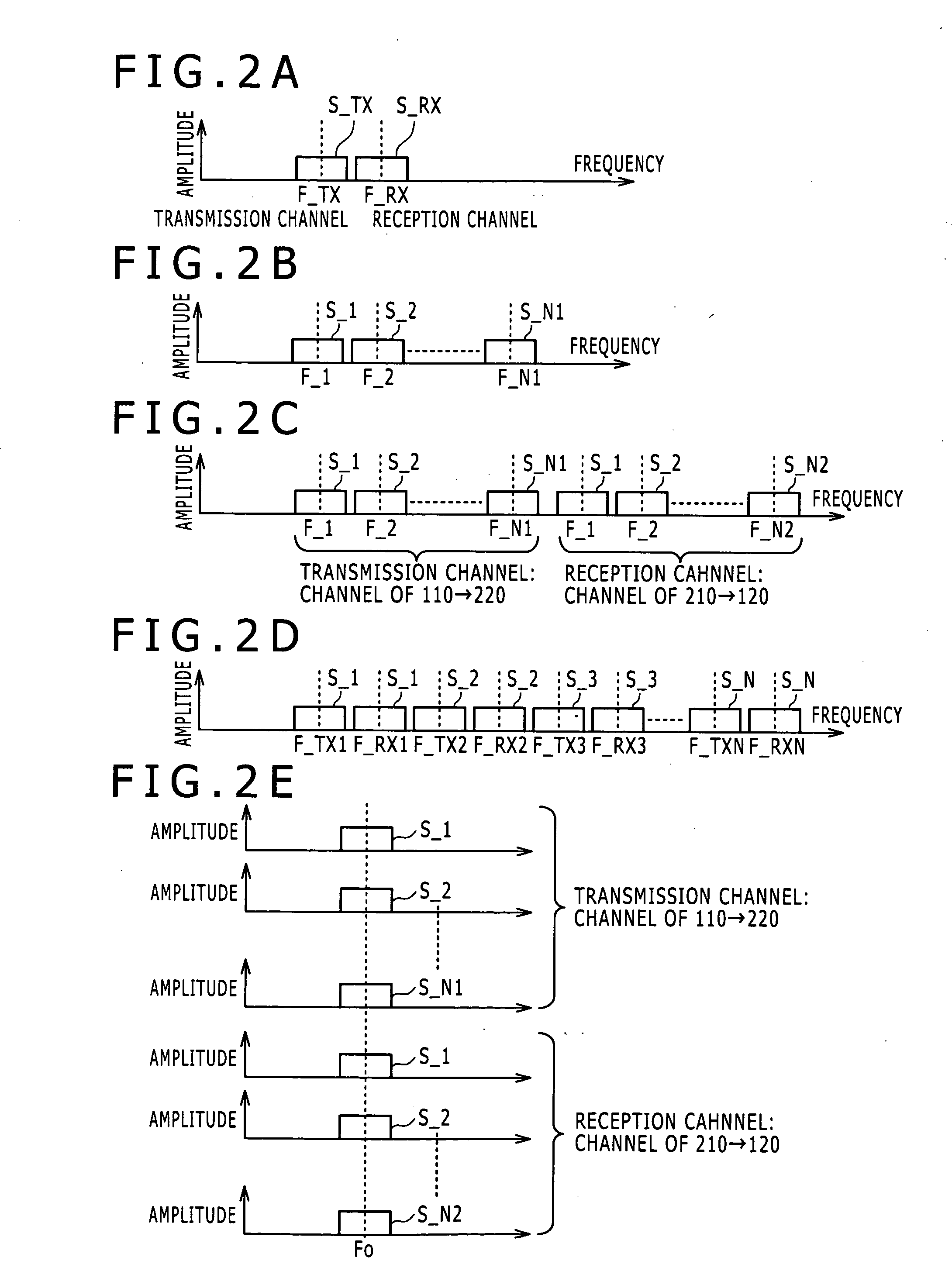
[0029]Preferably, a common frequency is used for the carrier signals. If the common frequency is used, then since the influences of the carrier frequencies in the channels become equal to each other with certainty, the MIMO process in the baseband region can be carried out with certainty and efficiently. In addition, in comparison with an alternative case wherein different carrier frequencies are used for the different channels, the circuit scale for modulation and demodulation can be reduced.

Problems solved by technology

However, together with further increase of the amount of transmission information and further increase of the speed of transmission recently, increase of power consumption, increase of an influence of signal distortion by reflection and so forth, increase of unnecessary radiation and so forth have become problems.
However, the countermeasure just described gives rise to increase of the number of input and output terminals.
As a result, complication of a printed board or a cable wiring scheme, increase of the size of a semiconductor chip and so forth are required.
Further, since a large amount of data is transmitted at a high speed along a wiring system, a problem of electromagnetic field interference occurs.
All of the problems involved in the LVDS or the technique of increasing the number of wiring lines are caused by transmission of a signal through an electric wiring line.
However, where the space division multiplexing is applied, an interference countermeasure between channels is required.

Method used


Image

  • Wireless transmission system, wireless communication device and wireless transmission method
  • Wireless transmission system, wireless communication device and wireless transmission method
  • Wireless transmission system, wireless communication device and wireless transmission method

Examples


first example

[Demodulation Functional Unit: First Example]

[0198]FIG. 5B shows a configuration of a demodulation functional unit 8400X of the first example provided on the reception side. While the demodulation functional unit 8400X can have various circuit configurations within a range corresponding to the modulation method on the transmission side, it is assumed here that the demodulation functional unit 8400X adopts a method applied where the amplitude is modulated so as to correspond to the description of the modulation functional unit 8300X given hereinabove. Where a method wherein the phase is modulated is to be adopted, the demodulation functional unit 8400X should be configured so as to be ready for quadrature detection or synchronous detection.

[0199]The demodulation functional unit 8400X of the first example includes a frequency mixer 8402 or mixer circuit of the 2-input type as an example of an amplitude detection circuit and uses a square-law detection circuit from which a detection ou...

second example

[Modulation Functional Unit: Second Example]

[0215]FIGS. 6A to 6D show a configuration of the second example of the modulation functional unit 8300 and peripheral circuits. Referring to FIGS. 6A to 6D, a modulation-subject signal processor 8301 is provided on the preceding stage to the modulation functional unit 8300, particularly to the frequency mixer 8302. FIGS. 6A to 6D particularly show different configuration examples matching with the digital type. Referring to FIGS. 6A to 6D, the modulation-subject signal processor 8301 carries out DC-free encoding such as 8-9 conversion encoding (8B / 9B encoding), 8-10 conversion encoding (8B / 10B encoding) or a scrambling process with respect to the data supplied from the parallel-serial converter 8114 in order to eliminate appearance of a DC component caused by successive appearances of the same code. Though not shown, in analog modulation, bypass filter processing or band-pass filter processing should be applied in advance to the modulation...


PUM


Abstract

Disclosed herein is a wireless transmission system including a plurality of antenna pairs; a demodulation functional unit; and a transmission characteristic correction unit. The plurality of antenna pairs each including a transmission antenna and a reception antenna. A wireless signal transmitted from a transmission antenna directly arrives as a desired wave at a corresponding reception antenna. Meanwhile, a wireless signal transmitted from a different transmission antenna directly arrives as an unnecessary wave at the reception antenna. The demodulation functional unit corresponding to each antenna pair demodulates a modulation signal received by the reception antenna. The transmission characteristic correction unit carries out correction calculation based on a transmission characteristic of a transmission space between the transmission and reception antennae based on demodulation signals demodulated by the demodulation functional units to acquire an output signal corresponding to a transmission subject signal.

Description

BACKGROUND OF THE INVENTION[0001]1. Field of the Invention[0002]This invention relates to a wireless transmission system (including also a wireless communication device implemented in one housing), a wireless communication device for the reception side and a wireless communication method. More particularly, the present invention relates to a mechanism wherein space division multiplexing is applied to wirelessly transmit a plurality of transmission subject signals.[0003]2. Description of the Related Art[0004]As a technique for implementing a high-speed signal transmission between different electronic apparatus disposed in a comparatively short range (for example, within several centimeters to ten and several centimeters), or within an electronic apparatus, for example, a LVDS (Low Voltage Differential Signaling) is known. However, together with further increase of the amount of transmission information and further increase of the speed of transmission recently, increase of power cons...

Claims


Application Information

Patent Timeline
IPC IPC(8): H04W24/02H04W72/04
CPCH04B7/0697H04B7/0682
Inventor MIHOTA, NORIHITO
Owner SONY CORP
Learn More