
Optimized control of power plants having air cooled condensers

Active Publication Date: 2011-03-17
EMERSON PROCESS MANAGEMENT POWER & WATER SOLUTIONS
View PDF5 Cites 125 Cited by
  • Summary
  • Abstract
  • Description
  • Claims
  • Application Information

AI Technical Summary

Benefits of technology

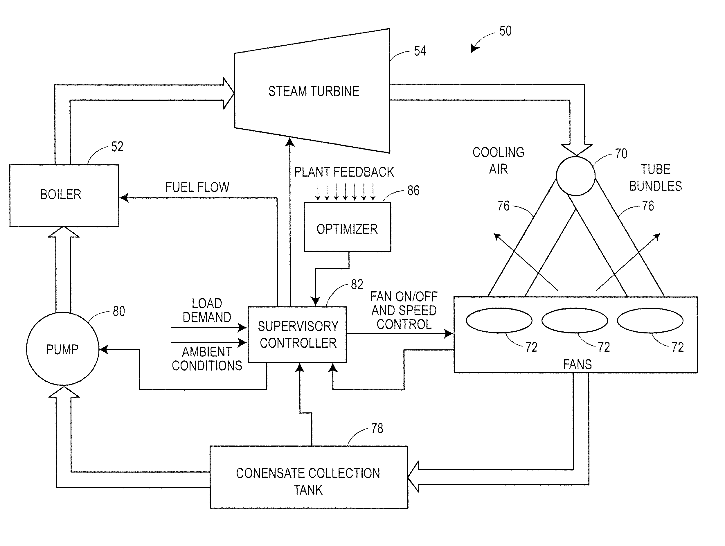
[0013]An optimization and control system for a utility plant that uses fan based air cooled condensers controls the operation of the power generation system at the plant in conjunction with the operation of the air cooled condensers so as to run the power plant at a more optimum operating point, e.g., to minimize or reduce the cost of each unit of useful energy, such as each kilowatt hour, produced by the plant. The optimization and control system includes an optimizer having a numerical solver that determines values for a set of control variables that defines an optimal operating point of the plant and an expert system that oversees and modifies the control variable settings prior to providing these settings to a plant controller. The output of the expert system is provided to the plant controller which then controls the plant to run at an optimal point as defined by the optimizer. In one embodiment, a numerical solver within the optimizer uses an objective function and one or more models of plant equipment to determine the best or most optimal operating point of the plant to, for example, minimize the cost per kilowatt-hour generated by the plant or minimize the cost of the production of other useful energy such as steam energy. As part of determining the optimal plant operating point, the numerical solver may determine the number of fans to run within the air cooled condensers of the plant and / or the speed of the fans to use in the air cooled condensers in conjunction with the amount of fuel to burn in the boiler or other thermal process, the desired temperature of the steam at the input of the steam turbine, etc., all required to produce a given amount of power (load demand) at the particular environmental conditions (e.g., temperature, humidity, etc.) currently experienced at the plant. The expert system may use or modify these outputs by determining which fans to actually use at any particular time based on, for example, the availability of or the operational status of the fans, the wear of the fans and fan motors, etc. The expert engine may then provide these modified outputs to the controller, which controls the plant to operate at the optimal operating point as specified by or associated with the outputs of the optimizer.

Problems solved by technology

While the electric utility plants which use these various different types of power generation methodologies operate using different implementation technologies, these plants are always operated under a set of constraints applicable to the particular methodology being applied.
One example of constraints encountered in these types of plants (i.e., power plants using boilers or other similar steam generation technologies) that affects the efficiency of the plant includes the set points of the steam temperature used at the final super-heater and re-heater outlets of the boilers.
If the steam temperature is too high, it may cause damage to the blades of the steam turbine for various metallurgical reasons.
On the other hand, if the steam temperature is too low, it may contain water particles which may also cause damage to components of the steam turbine.
Unfortunately, water is often a limited or scarce resource, and thus may not be in sufficient supply at any particular power plant site.
Many countries, such as China, are very concerned about stressing water supplies and so have limited the use of water in these types of power plants.
In some regions, especially dry and arid regions, the use of lake and river water is tightly regulated, and so it may not be possible, or it may be very costly to use a large amount of fresh water in a power plant cooling system.
Still further, once-through cooling systems, while consuming very little water because they return most of the water to the source, still heat up the water, which in many cases leads to undesirable environmental impacts.
However, the large volume of water withdrawn by a once-through cooling system can entrain and impinge aquatic organisms, and discharges heat to surface waters which may have adverse ecological effects.
As a result, most United States jurisdictions now discourage or prohibit construction of new power plants that use once-through water cooling systems.
However, because re-circulating cooling systems cool by evaporation in towers or cooling ponds, they consume more water than once-through cooling systems.
Moreover, in re-circulating cooling systems, the cost to treat and dispose of cooling water varies much more widely, depending on the characteristics of the raw water being used.
While effluent from wastewater treatment plants, which is typically treated to make it suitable for discharge, is usually of fairly high quality, nutrients and bacteria may restrict the use of wastewater in a cooling system unless this water is pre-treated in the power plant.
For example, low pH is an issue for water pumped from spent coal mines, and the effluent of oil and gas well operations can have high levels of salts, silica, and hardness.
In any event, because water is becoming a scarce commodity, and the use of water in re-circulating cooling systems can be expensive, plant designers are, more and more, considering direct dry cooling systems, also called air cooled condensers.
However, the large size of the hyperbolic tower makes the natural draft option a niche application and this type of cooling system is typically only able to be economically used at small power plant sites.
Single speed fans do exist, however, as they create a lower installed cost, which is sometimes the only concern of the plant designer.
In any event, if single speed, multiple speed or continuously variable speed fans are used within a plant, the optimum combination of fans to run in any particular situation other than the designed maximum load condition, and speed at which to run these fans to obtain the appropriate cooling within the re-circulating system is generally unknown and not easily predicted, as it involves solving for an elusive multidimensional point in the operational space of the cooling system.
Moreover, changing the speed of and the number of fans running within a condenser system may change the backpressure at the steam turbine, resulting in a less than expected or designed heat rate, which is typically used as the measure of plant efficiency.
Thus, while utility plants that use electric powered air cooled condensers are designed to have enough fans to operate at full load and at the worst ambient conditions (e.g., the highest ambient temperature, worst humidity, etc.), operators generally do not have any ability to gauge how many fans to use, and at what speed to run the fans, at lower then maximum load and / or at more favorable ambient conditions.
Unfortunately, running the electric fans of the air cooled condensers uses electric energy (created by the plant) and thus reduces the final output of the electric plant, thereby increasing the cost of the electrical power generation being performed.
Standard methods of operating the air cooled condensers therefore typically result in a plant being less efficient than is possible, resulting in higher costs to run the plant for a given energy output.

Method used


Image

  • Optimized control of power plants having air cooled condensers
  • Optimized control of power plants having air cooled condensers
  • Optimized control of power plants having air cooled condensers

Examples


Embodiment Construction

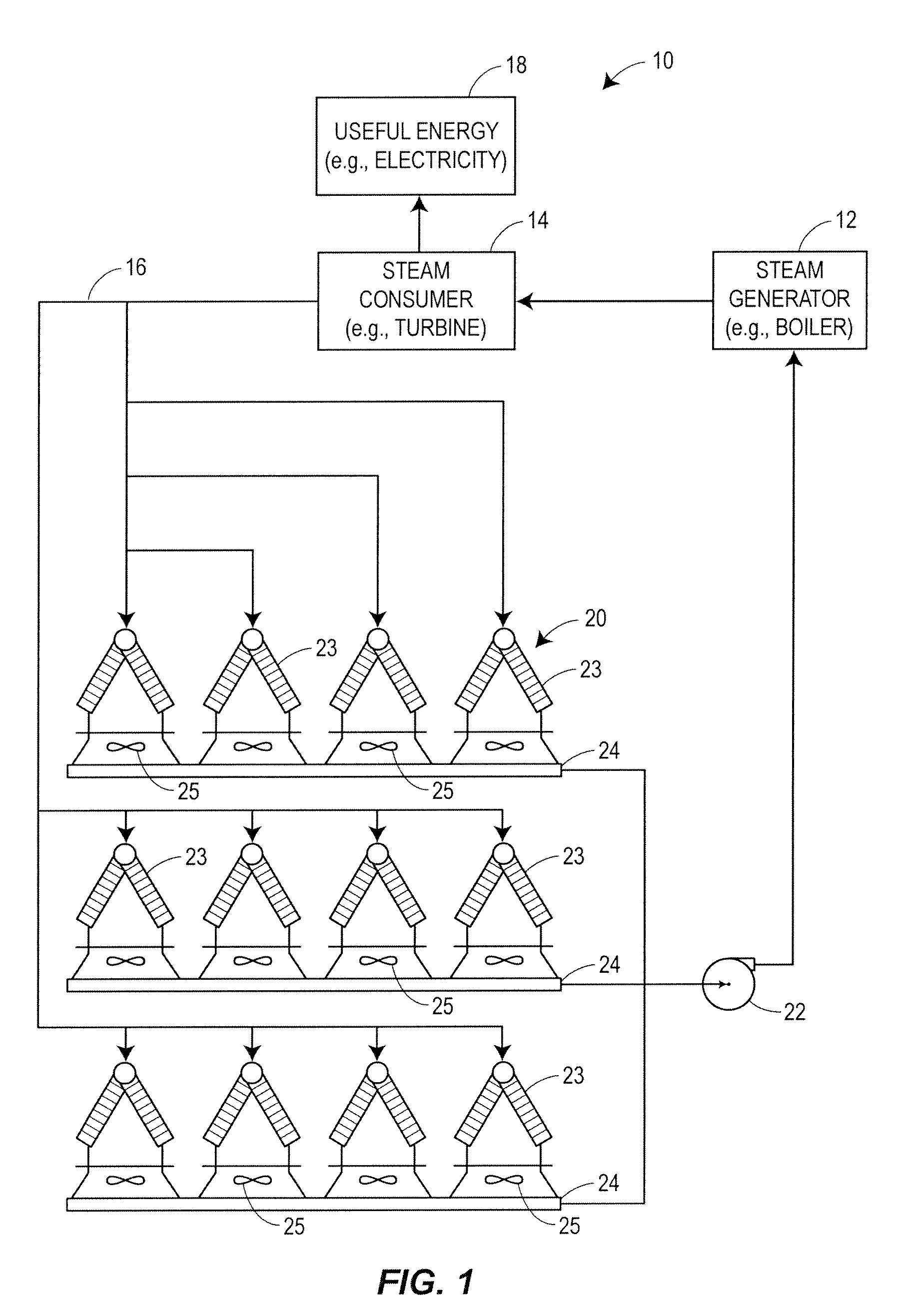
[0020]Referring now to FIG. 1, a block diagram of a steam cycle of a typical energy generation system 10 includes a steam generator 12 and a steam consumer 14 (typically in the form of a steam turbine) which generates useful energy 18. The steam consumer 14 is connected within a closed re-circulating loop 16 to a set of electrical fan-operated, air cooled condensers 20. The re-circulating loop 16, which may be made of suitable pipes and ducts for carrying steam and water, also includes one or more boiler feed pumps 22 which return liquid (e.g., water) formed in the condensers 20 to the steam generator 12.

[0021]Although the steam generator 12 is described herein as a boiler system that operates using thermal principles (e.g., by burning fuel such as petroleum, waste fuel, biomass, wood chips, etc.), to turn water into steam, other types of steam generators could be used instead of or in addition to a boiler system. For example, the steam generator 12 could be a fossil fueled boiler (...


PUM


Abstract

An optimization and control system for a utility plant that uses fan based air cooled condensers controls the operation of the power generation system at the plant in conjunction with the operation of the air cooled condensers so as to run the power plant at an optimum operating point associated with minimizing or reducing the cost of each kilowatt-hour of energy or other useful energy produced by the plant. The optimization and control system includes an optimizer having a numerical solver that determines values for a set of control variables associated with an optimal operating point of the plant and an expert system that oversees and modifies the control variable settings prior to providing these settings to a plant controller. The numerical solver uses an objective function and one or more models of plant equipment to determine the operating point of the plant that minimizes the cost per unit of useful energy generated by the plant. As part of determining the optimal plant operating point, the numerical solver may determine the number of fans to run within the air cooled condensers of the plant and / or the speed of the fans to use in the air cooled condensers in conjunction with the amount of fuel to burn in the boiler, the desired temperature of the steam at the input of the steam turbine, etc., all required to produce a given amount of power (load demand) at the particular environmental conditions currently experienced at the plant. The expert system may modify these outputs by determining which fans to actually use at any particular time based on, for example, the availability of or the operational status of the fans, the wear of the fans and fan motors, etc.

Description

TECHNICAL FIELD[0001]This patent relates generally to control systems used to control utility or power plant operations, and more particularly to a control system that performs optimal control of a utility or power plant that includes air cooled condensers.BACKGROUND[0002]Electric power or utility plants generate electricity using any of a number of different types of power generation methodologies, and are typically categorized based on the type of raw energy they use to generate electrical power. Electrical power generation methodologies include, for example, thermal, nuclear, wind, and hydroelectric energy conversion methodologies, to name but a few. While the electric utility plants which use these various different types of power generation methodologies operate using different implementation technologies, these plants are always operated under a set of constraints applicable to the particular methodology being applied. For example, the electrical output of a thermal generator ...

Claims


Application Information

Patent Timeline
IPC IPC(8): G05B13/04G06N5/02
CPCF01K9/003G05B13/041F01K13/02Y02E30/00F28B1/06G05B13/02
Inventor FRANCINO, PETER N.HUFF, FREDERICK C.WINN, HARRY R.FOSTER, DAVID G.
Owner EMERSON PROCESS MANAGEMENT POWER & WATER SOLUTIONS
Learn More