Translucent polycrystalline sintered body, method for producing the same, and arc tube for high-intensity discharge lamp

a technology of translucent polycrystalline sintered body and arc tube, which is applied in the direction of gas-filled discharge tubes, solid cathodes, domestic applications, etc., can solve the problems of poor in-line transmittance of arc tube of conventional translucent alumina, inferior qualities of conventional ceramic bodies using only mgo, and inability to produce satisfactory results, etc., to achieve high in-line light transmittance, high bending strength, and high translucency

Inactive Publication Date: 2011-03-10
NGK INSULATORS LTD
View PDF13 Cites 8 Cited by
  • Summary
  • Abstract
  • Description
  • Claims
  • Application Information

AI Technical Summary

Benefits of technology

[0039]As described above, the translucent polycrystalline sintered body of the present invention, obtainable by the method of the present invention, has a high in-line light transmittance and a high bending strength, and thereby is suitable for the manufacture of an arc tube for a high-intensity discharge lamp u

Problems solved by technology

However, the combination use of MgO, Y2O3, and La2O3 cannot produce satisfactory results, and rather the conventional ceramic bodies using the combination are inferior in qualities to ceramic bodies using only MgO.
However, in a high-intensity discharge lamp, the arc tube of the conventional translucent alumina is generally poor in in-line transmittance due to grain boundary birefringence, etc.
When a light is emitted from a position other than the focal position, the desired light distribution characteristics cannot be obtained, resulting in optical design difficulty.
It is difficult to control the light from the diffused light source by using the reflecting mirror or lens.
Therefore, it is difficult to use the above discharge lamp in combination with the reflecting mirror in an optical device, and the use of the discharge lamp is limited to general lighti

Method used


Image

  • Translucent polycrystalline sintered body, method for producing the same, and arc tube for high-intensity discharge lamp
  • Translucent polycrystalline sintered body, method for producing the same, and arc tube for high-intensity discharge lamp
  • Translucent polycrystalline sintered body, method for producing the same, and arc tube for high-intensity discharge lamp

Examples


example 1

[0122]A slurry was prepared by mixing the following components.

(Raw Material Powder)

[0123]100 parts by weight of an α-alumina powder having a specific surface area of 3.5 to 4.5 m2 / g and an average primary grain diameter of 0.35 to 0.45 μm

[0124]0.025 parts by weight of MgO (magnesia)

[0125]0.040 parts by weight of ZrO2 (zirconia)

[0126]0.0015 parts by weight of Y2O3 (yttria)

(Dispersion Medium)

[0127]27 parts by weight of dimethyl glutarate

[0128]0.3 parts by weight of ethylene glycol

(Gelling Agent)

[0129]4 parts by weight of an MDI resin

(Dispersing Agent)

[0130]3 parts by weight of a macromolecular surfactant

(Catalyst)

[0131]0.1 part by weight of N,N-dimethylaminohexanol

[0132]The slurry was cast into an aluminum alloy mold at the room temperature. The slurry was left in the mold at the room temperature for 1 hour and at 40° C. for 30 minutes to perform solidification. The resultant solid was separated from the mold, and was let stand at the room temperature for 2 hours and at 90° C. for 2 ...

example 2

[0139]A slurry was prepared in the same manner as Example 1 except for using 0.0030 parts by weight of Y2O3.

[0140]The slurry was cast into an aluminum alloy mold at the room temperature. The slurry was left in the mold at the room temperature for 1 hour and at 40° C. for 30 minutes to perform solidification. The resultant solid was separated from the mold, and was let stand at the room temperature for 2 hours and at 90° C. for 2 hours, to obtain plate-shaped and rod-shaped powder compacts.

[0141]Each of the obtained powder compacts was calcined at 1100° C. in the air, and fired twice at 1800° C. in a hydrogen / nitrogen ( 3 / 1) atmosphere, to increase the density and translucency of the compact. Thus, a plate-shaped sintered body, an arc tube-shaped sintered body, and a rod-shaped sintered body, respectively having the same sizes as those of Example 1 were produced.

[0142]The average grain diameter of each sintered body was measured by the above described average grain diameter calculati...

example 3

[0147]A slurry was prepared in the same manner as Example 1 except for using 0.0045 parts by weight of SiO2 (silica), 0.003 parts by weight of Na2O (sodium oxide), and 0.002 parts by weight of K2O (potassium oxide) in addition to the components of Example 1.

[0148]The slurry was cast into an aluminum alloy mold at the room temperature. The slurry was left in the mold at the room temperature for 1 hour and at 40° C. for 30 minutes to perform solidification. The resultant solid was separated from the mold, and was let stand at the room temperature for 2 hours and at 90° C. for 2 hours, to obtain plate-shaped and rod-shaped powder compacts.

[0149]Each of the obtained powder compacts was calcined at 1100° C. in the air, and fired once at 1800° C. in a hydrogen / nitrogen ( 3 / 1) atmosphere, to increase the density and translucency of the compact. Thus, a plate-shaped sintered body, an arc tube-shaped sintered body, and a rod-shaped sintered body, respectively having the same sizes as those o...


PUM

PropertyMeasurementUnit
Temperatureaaaaaaaaaa

Abstract

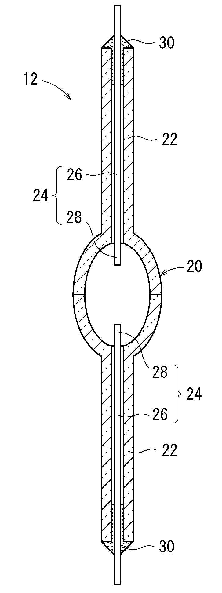
A translucent polycrystalline sintered body is mainly composed of an alumina, is suitable for the manufacture of an arc tube for a high-intensity discharge lamp, and has an average grain diameter of 35 to 70 μm, preferably 50 to 60 μm. In a case where the sintered body is in a 0.5-mm-thick flat plate shape, the in-line transmittance of the sintered body is 30% or more, preferably 50% or more. In this case, the ratio between maximum and minimum in-line transmittance values is 2:1 to 1:1 in the visible region of 360 to 830 nm. The bending strength of the sintered body is 250 MPa or more, preferably 300 MPa or more.

Description

CROSS-REFERENCE TO RELATED APPLICATION[0001]This application is based upon and claims the benefit of priority from Japanese Patent Applications No. 2009-207941 filed on Sep. 9, 2009 and No. 2009-234874 filed on Oct. 9, 2009, of which the contents are incorporated herein by reference.BACKGROUND OF THE INVENTION[0002]1. Field of the Invention[0003]The present invention relates to a translucent polycrystalline sintered body suitable for the manufacture of an arc tube for a high-intensity discharge lamp (HID: High Intensity Discharged lamp) such as a high-pressure sodium vapor lamp or a metal halide lamp. The invention further relates to a method for producing the translucent polycrystalline sintered body and an arc tube for high-intensity discharge lamp containing the translucent polycrystalline sintered body.[0004]2. Description of the Related Art[0005]A method described in Japanese Patent No. 2780941 is known as a technology for improving the load capacity of a sintered ceramic body ...

Claims


Application Information

Patent Timeline
IPC IPC(8): C04B35/505C04B35/10
CPCC04B35/115H01J61/302C04B35/6264C04B35/6303C04B35/64C04B2235/3201C04B2235/3206C04B2235/3225C04B2235/3244C04B2235/3418C04B2235/5409C04B2235/5445C04B2235/549C04B2235/6023C04B2235/6581C04B2235/6582C04B2235/661C04B2235/663C04B2235/784C04B2235/786C04B2235/94C04B2235/95C04B2235/96C04B2235/963C04B35/6263
Inventor MIYAZAWA, SUGIOWATANABE, KEIICHIROOHASHI, TSUNEAKIYAMAMOTO, HISANORI
Owner NGK INSULATORS LTD
Why Eureka
Try Eureka