
Infrared reflective laminate

Inactive Publication Date: 2011-02-24
TECHNO POLYMER CO LTD
View PDF5 Cites 21 Cited by
  • Summary
  • Abstract
  • Description
  • Claims
  • Application Information

AI Technical Summary

Benefits of technology

[0014]The present invention aims at providing an infrared reflective layered product which has a property of reflecting an infrared radiation with a specific wavelength so as to prevent heat storage even with black colored or chromatically colored appearance, and also, is small in thermal deformation and excellent in heat resistance, and further, is difficult to hydrolyze and excellent in weatherability even when used outside for a long time, difficult to crack and excellent in flexibility even in a form of film, and good in processability, productivity and handleability.

Problems solved by technology

However, the conventional black back sheet for solar cells is generally molded by kneading a carbon black into a resin, and thus the carbon black absorbs sunlight and increases the temperature.
In addition, a back sheet for solar cells provided on a surface thereof with a black resin layer containing a perylene pigment and having a light reflectance at a wavelength of 800 to 1100 nm of 30% or higher so as to reflect near-infrared light and prevent heat storage is also proposed (Patent Document 4), but since the substrate thereof is made of a polyethylene terephthalate film, it is inferior in weatherability and hydrolytic resistance disadvantageously.

Method used


Image

  • Infrared reflective laminate
  • Infrared reflective laminate
  • Infrared reflective laminate

Examples


example 11-8

3-6. Example 11-8

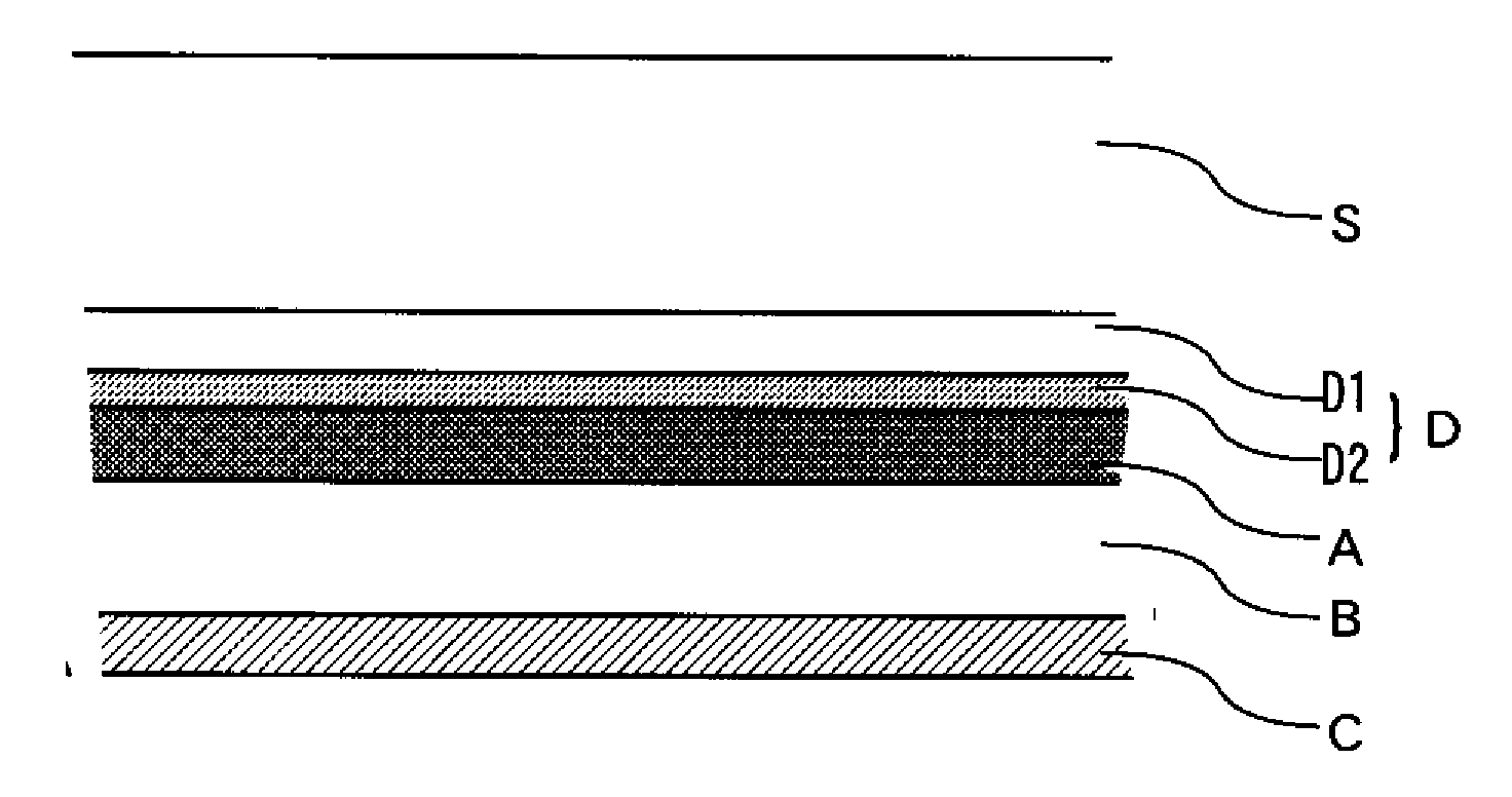
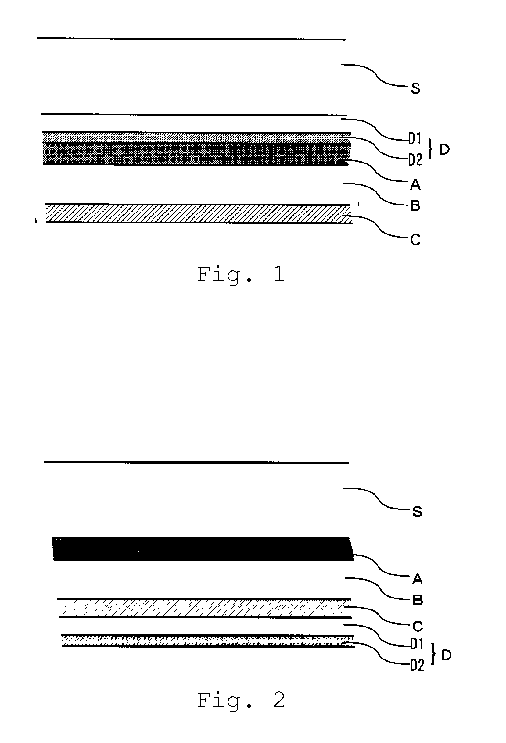
[0261]A film was produced in the same manner as in Example II-2 except that a water vapor barrier layer (D) was layered on the outer surface of the layer (C). In this instance, the layer (D) was layered so that the thin film layer (water vapor barrier layer) of the water vapor barrier film constituting the layer (D) was positioned to form the outermost surface. That is, the layered product with a structure shown in FIG. 2 was obtained.

[0262]Using the resulting film and the film obtained in Example II-2 as test pieces, flame resistance and scratch resistance were evaluated in accordance with the above methods. The results are shown in Table 9.

example 11-9

3-7. Example 11-9

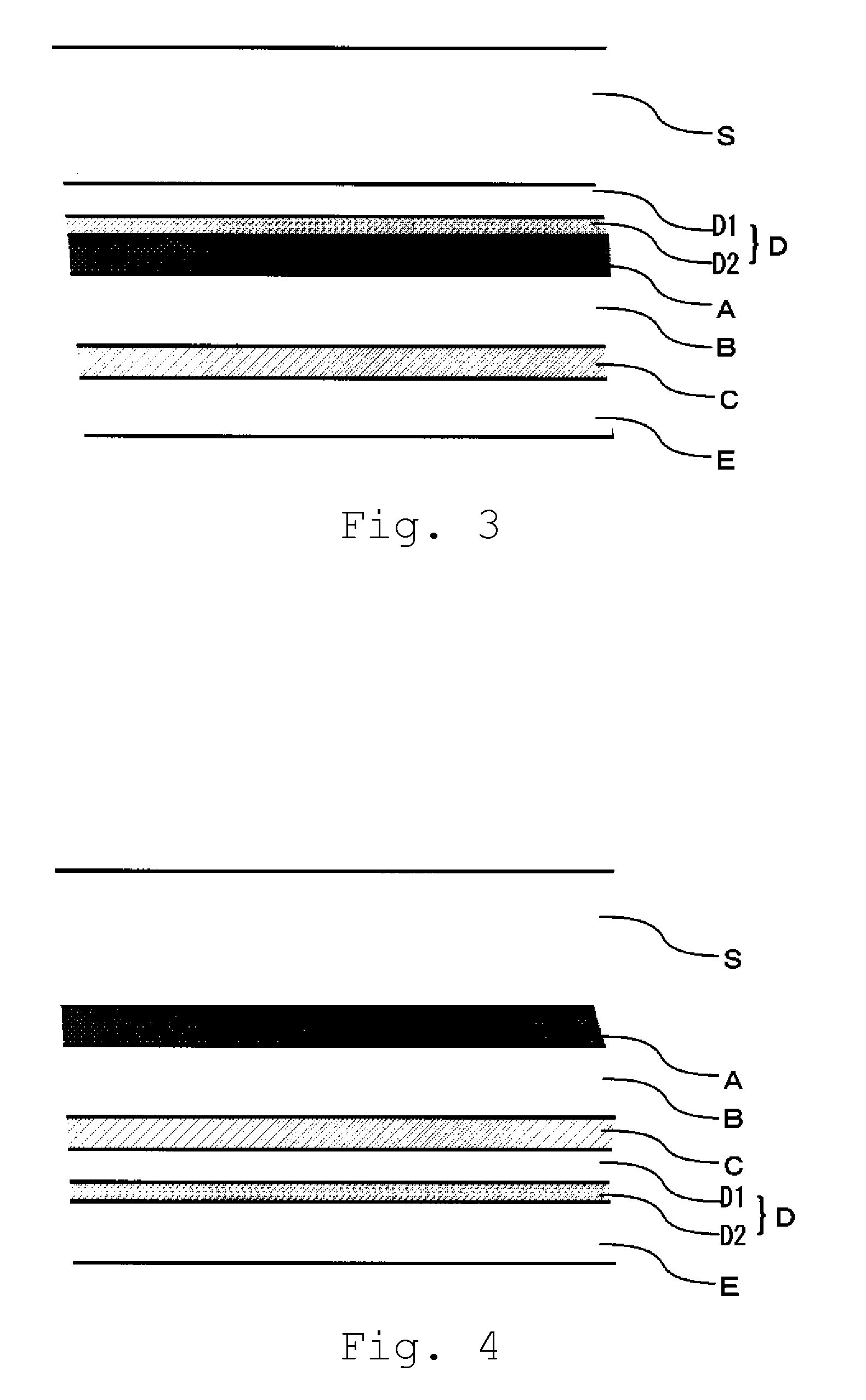
[0263]A PET film of Table 9 was stuck as the protective layer (E) on the outer surface of the layer (C) of the film obtained in Example II-2 using a polyurethane adhesive agent (painting thickness: 8 μm). That is, the layered product with a structure shown in FIG. 3 was obtained.

[0264]Using the resulting film as a test piece, flame resistance and scratch resistance were evaluated in accordance with the above methods. The results are shown in Table 9.

example ii-10

3-8. Example II-10

[0265]A PET film of Table 9 was stuck as the protective layer (E) on the outer surface of the layer (D) of the film obtained in Example II-8 using a polyurethane adhesive agent (painting thickness: 8 μm). That is, the layered product with a structure shown in FIG. 4 was obtained.

[0266]Using the resulting film as a test piece, flame resistance and scratch resistance were evaluated in accordance with the above methods. The results are shown in Table 9.

TABLE 9ExampleExampleExampleExampleII-2II-8II-9II-10Material of thenonenone(E-1)(E-1)protective layer(E)Scratch resistanceΔΔ◯◯Flame resistanceXX◯◯

[0267]From Table 9, it is found that scratch resistance and flame resistance are improved by laminating a protective layer (E) of the present invention on the outer surface of the layer (C), and this is preferable.


PUM

PropertyMeasurementUnit
Temperatureaaaaaaaaaa
Fractionaaaaaaaaaa

Abstract

This invention provides an infrared reflective layered product, particularly a back sheet for solar cells, which, even when it has a black colored or chromatically colored appearance, can reflect infrared radiation with certain wavelengths to prevent heat accumulation and, at the same time, has excellent heat resistance. The infrared reflective layered product comprises the following layer (B) as a base layer, the following layer (A) layered on one side of the layer (B), and the following layer (C) layered on the other side of the layer (B).Layer (A): a colored resin layer which has an absorptance of a light with a wavelength of 800-1400 nm of not more than 10%.Layer (B): a thermoplastic resin layer which shows a dimensional change (s) satisfying 1%≧s≧−1% when left at 150° C. for 30 minutes.Layer C: a colored resin layer having a reflectance of a light with a wavelength of 400-1400 nm of not less than 50%.Preferably, the layer (A) is formed of a resin containing an infrared transmittable coloring agent, and the layer (C) is formed of a resin containing a white pigment. A water vapor barrier layer (D) may be additionally provided.

Description

TECHNICAL FIELD[0001]The present invention relates to a layered product having a property of absorbing a visible light and reflecting an infrared light so as to prevent heat storage when irradiated with light and excellent in heat resistance, and further relates to an infrared reflective layered product excellent in weatherability, hydrolytic resistance and flexibility. Also, the present invention further relates to an infrared reflective layered product which is excellent in water vapor barrier property and / or prevented from curling.BACKGROUND ART[0002]Recently, there is a growing demand for solar cells that have been noticed as energy supplying means alternative to petroleum which is a cause of global warming. With the increase in demand for solar cells, stable supply and cost reduction of parts such as back sheets for solar cells have been required, and also there is a growing demand for improving power generation efficiency of solar cells.[0003]Back sheets for solar cells are la...

Claims


Application Information

Patent Timeline
IPC IPC(8): F21V9/04B32B7/023
CPCB32B7/02B32B17/10018B32B17/10788Y10T428/2495B32B2325/00H01L31/048Y02E10/50B32B27/08B32B25/08B32B25/14B32B25/20B32B27/30B32B27/32B32B2307/306B32B2307/4026B32B2307/412B32B2307/416B32B2307/712B32B2307/7246B32B2307/7265B32B2457/12H01L31/049Y10T428/31931Y10T428/31935Y10T428/31663Y10T428/31721Y10T428/31938B32B7/023
Inventor WATANABE, ATSUSHIHASHIMOTO, MASANORIKAKUNO, WATARU
Owner TECHNO POLYMER CO LTD
Learn More