
Vehicle seat armrest assembly

Inactive Publication Date: 2006-06-08
RUSPA OFFICINE
View PDF13 Cites 15 Cited by
  • Summary
  • Abstract
  • Description
  • Claims
  • Application Information

AI Technical Summary

Benefits of technology

[0007] It is an object of the present invention to provide an armrest assembly designed to eliminate the aforementioned drawbacks, and which is cheap and easy to produce.

Problems solved by technology

For the same reason, replacement of any damaged parts is relatively expensive.

Method used


Image

  • Vehicle seat armrest assembly
  • Vehicle seat armrest assembly
  • Vehicle seat armrest assembly

Examples


Embodiment Construction

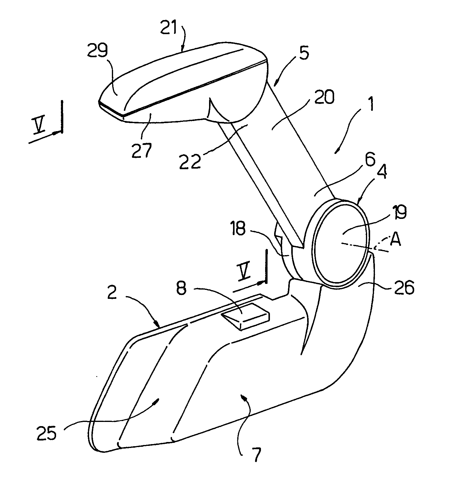
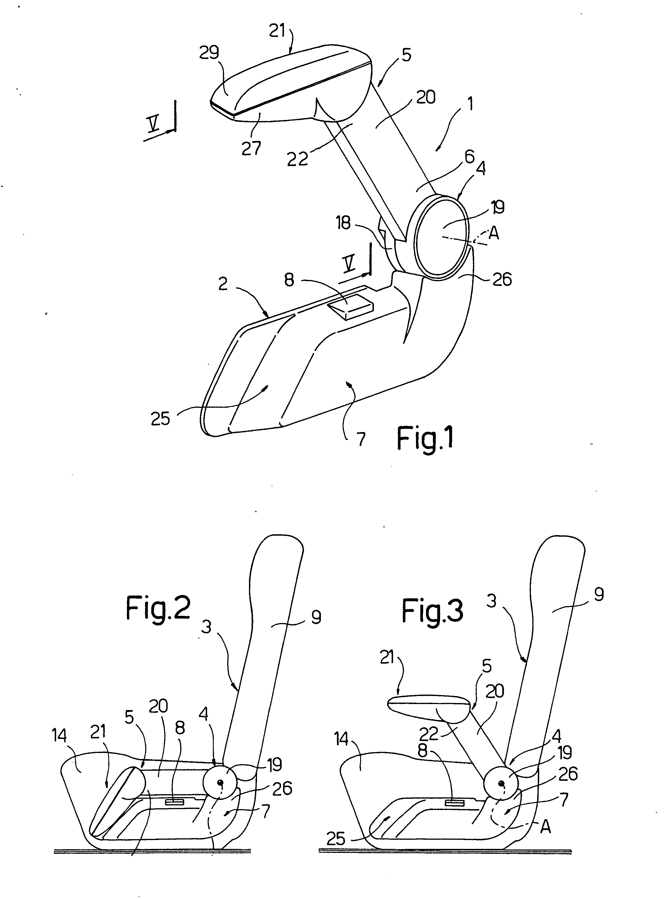
[0015] Number 1 in FIG. 1 indicates as a whole an armrest assembly comprising a flat fastening plate 2 which is fitted removably to a lateral portion of a bus seat 3; a hinge device 4 connected removably to plate 2; and an armrest 5 having an end portion 6 connected to hinge device 4 and rotating about an axis A perpendicular to plate 2.

[0016] The armrest assembly also comprises a lateral cover plate 7 fitted removably to plate 2 and housing a control block 8 for adjusting the tilt of a backrest 9 of seat 3.

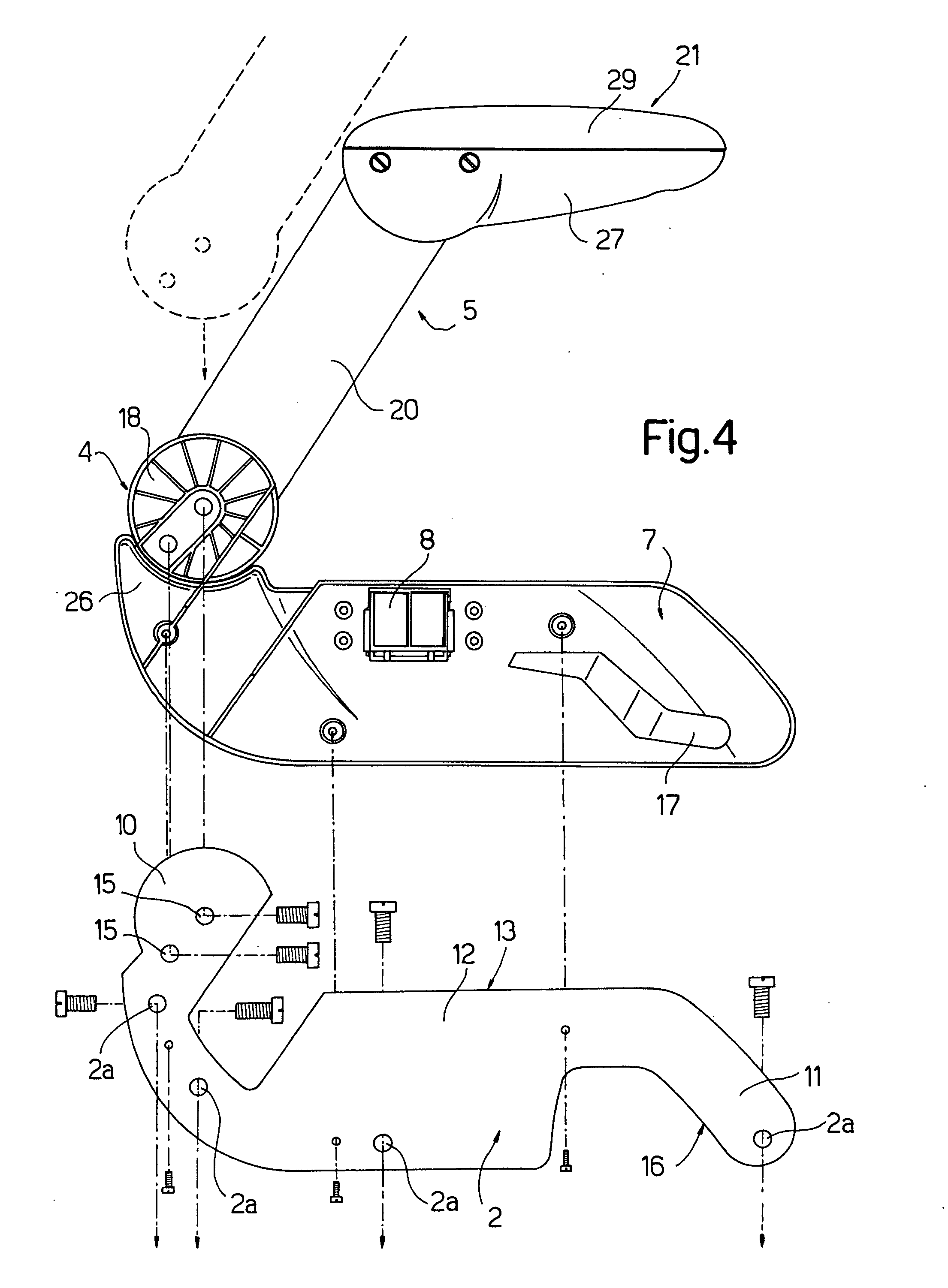
[0017] More specifically (FIG. 4), plate 2 is elongated in shape, and comprises a number of holes 2a for connection to seat 3, and a first and second curved end portion 10, 11 substantially forming an S with a rectangular central reinforcing plate 12 having a straight longitudinal edge 13 substantially parallel, in use, to a seat portion 14 of seat 3.

[0018] First curved portion 10 projects with respect to longitudinal edge 13, and has two holes 15 for connection to hinge devic...


PUM


Abstract

An armrest assembly having a fastening plate connected to a vehicle seat; a hinge device connected to the fastening plate; and an armrest connected removably to the hinge device and movable between a work position, in which the armrest is tilted and projects with respect to the fastening plate, and a collapsed position, in which the armrest is adjacent to the fastening plate.

Description

CROSS-REFERENCE TO RELATED APPLICATIONS [0001] This application claims the benefit of Italian Patent Application Number T02004A 000815, filed on Nov. 19, 2004, the contents of which are incorporated by reference herein. BACKGROUND OF THE INVENTION [0002] 1. Field of the Invention [0003] The present invention relates to an armrest assembly for a vehicle, e.g. bus, seat. [0004] An armrest assembly comprises a fastening plate connected laterally to a bus seat; and a rotary armrest hinged to the fastening plate and movable between a work position, in which the armrest supports the passenger's arm, and a collapsed position, in which the armrest is rotated towards a seat portion of the seat to allow the passenger to exit easily. [0005] 2. Description of the Related Art [0006] Armrest assemblies are normally formed in one piece and specially designed for a given bus interior, so that each new interior design calls for redesigning and high-cost retooling of new production lines. For the sam...

Claims


Application Information

Patent Timeline
IPC IPC(8): A47C7/54B60N2/75
CPCB60N2/242B60N2/4606B60N2/4673B60N2/753B60N2/787
Inventor RUSPA, LUIGI
Owner RUSPA OFFICINE
Learn More