
Self-drilling fastening element

Inactive Publication Date: 2010-11-11
HILTI AG
View PDF10 Cites 17 Cited by
  • Summary
  • Abstract
  • Description
  • Claims
  • Application Information

AI Technical Summary

Benefits of technology

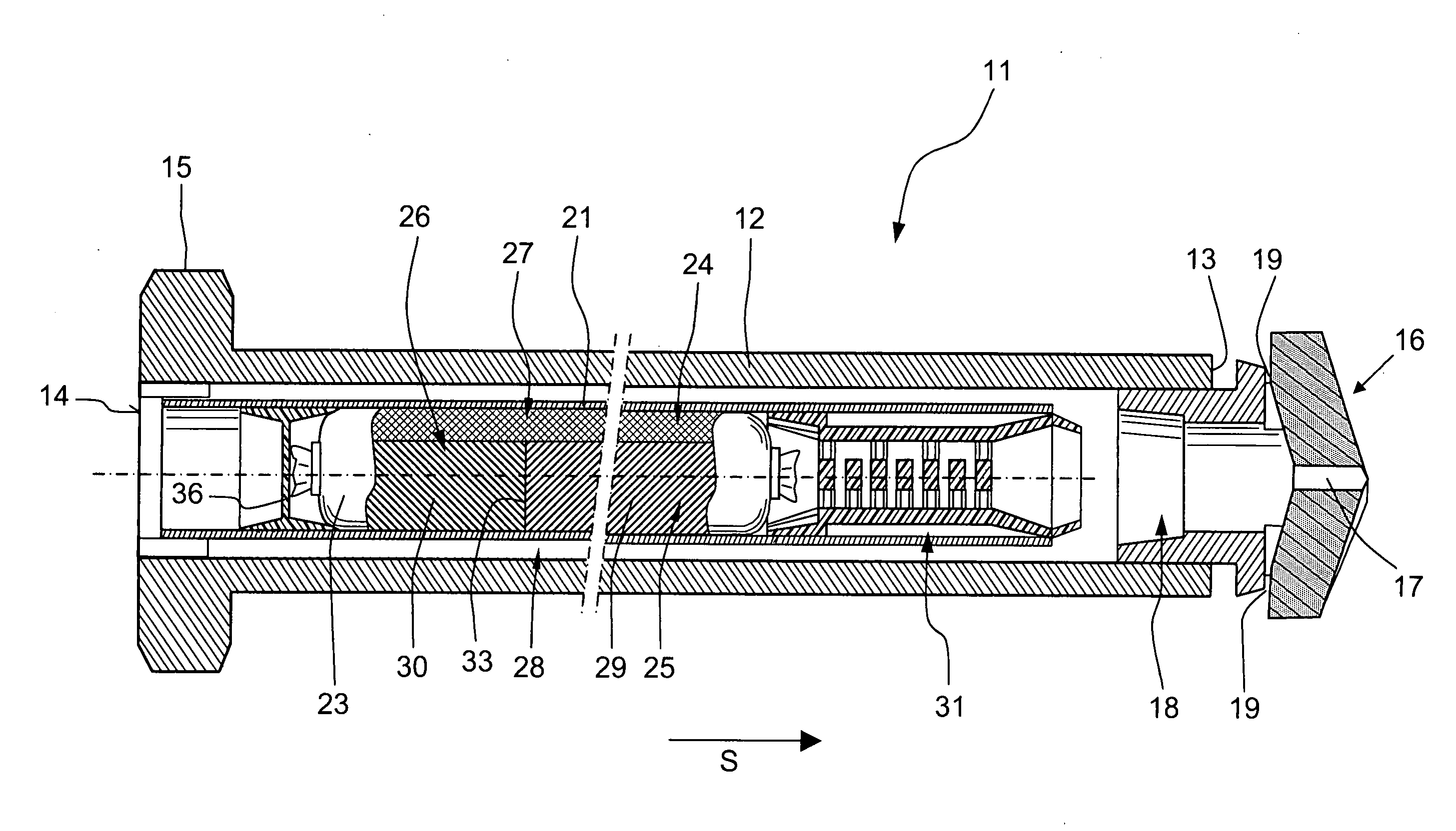
[0013]After a complete ejection of the components of the hardenable mass, there are available two hardenable mixtures of the hardenable mass having different hardening speeds. The firstly pouring-out first mixture hardens with slower speed and insures a subsequent pouring-out of the second mixture. The second mixture, which pours out after the first mixture, hardens more rapidly than the first mixture and, advantageously, right away. Thereby, it is insured that the fastening element is anchored in the constructional component more rapidly and reliably. The rapidly hardenable mixture is located in the region of the borehole bottom, which insures an advantageous introduction or transfer of force in the constructional component.
[0026]Advantageously, the different formulations of the reactive resin are located in a through-chamber of the tubular film bag extending in a longitudinal direction of the tubular film bag. With this arrangement of the components, the tubular film bag has an advantageously small cross-section and can be easily produced. To exclude an undesirable reaction of the formulations with each other during a storage condition of the fastening element, advantageously, a separation wall is provided between the formulations in the corresponding chamber of the tubular film bag. The separation wall preferably, is easily openable or can be destructed, e.g., under pressure.

Problems solved by technology

The drawback of the known solution consists in that firstly, a borehole should be formed with a separate tool, and the insertion of two tubular bags in each borehole is expensive.
In addition, inadvertently, the tubular bags can be inserted in a borehole in incorrect order, so that upon setting of the fastening element, firstly, the tubular bag with a rapidly hardenable composition is destructed.
As a result, a correct setting of the fastening element is not possible any more or possible only to a limited extent.
The drawback of the fastening element of U.S. Pat. No. 4,055,051 consists in that the fastening elements cannot be loaded until the hardenable mass hardens.

Method used


Image

  • Self-drilling fastening element
  • Self-drilling fastening element
  • Self-drilling fastening element

Examples


Embodiment Construction

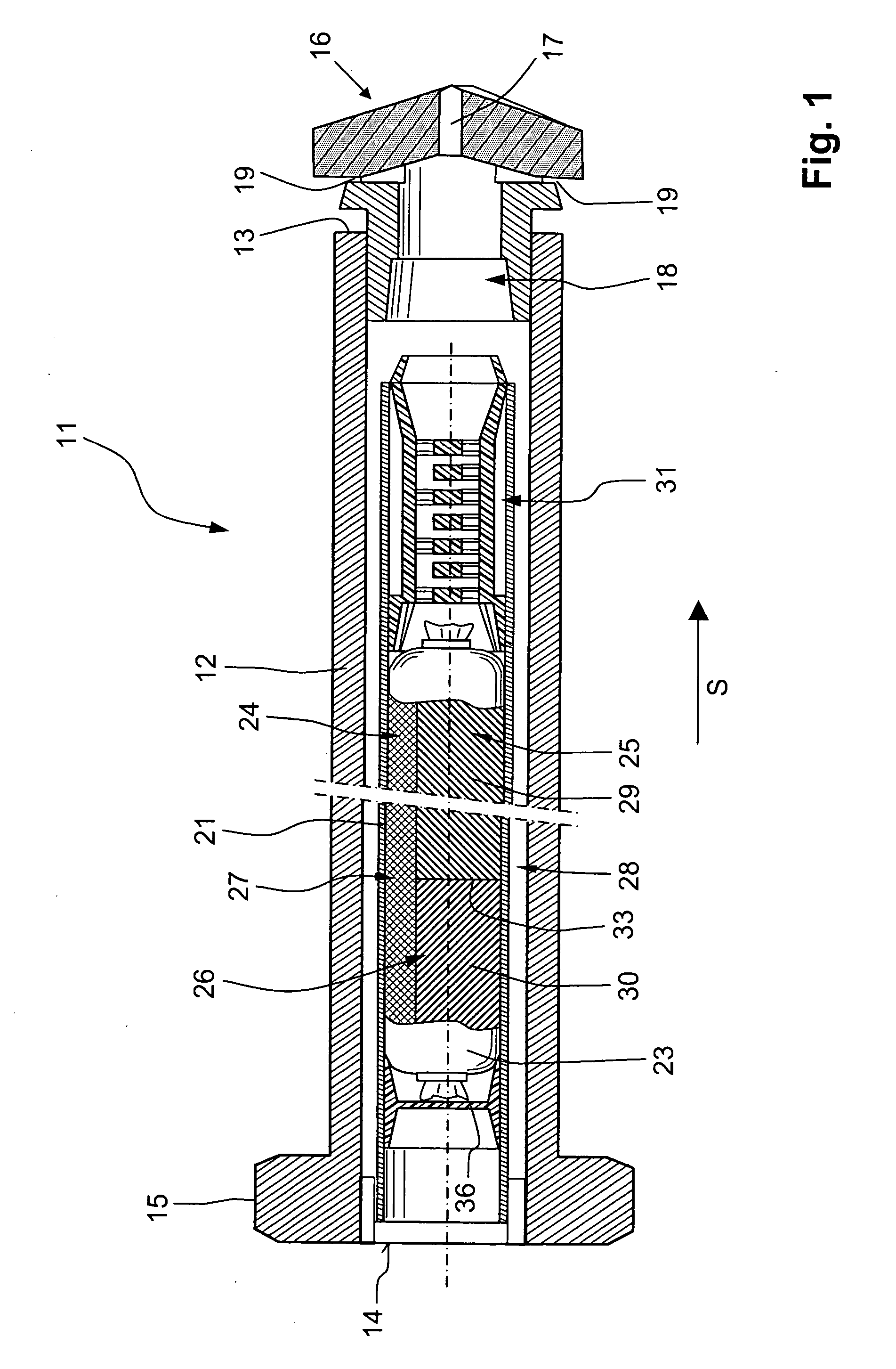
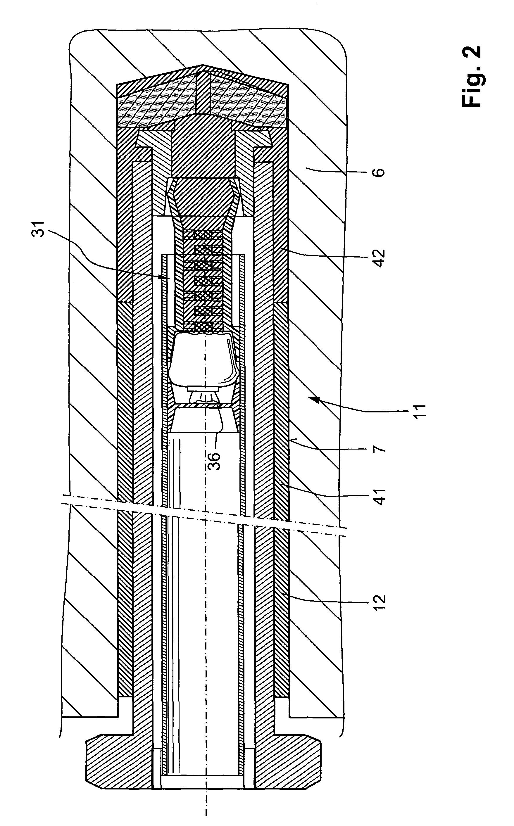
[0032]A self-drilling fastening element 11, which is shown in FIG. 1 and is formed as a rock anchor, has a hollow cylindrical receiving body 12 provided, at its end 13 facing in a setting direction S, with a drilling head 16 and, at its opposite end 14, with rotation transmitting means 15, e.g., in form of a polygon connectable with a drilling tool, not shown. The drilling head 16 has a first through-opening 17 and two, opening radially outwardly, second openings 19. There is further provided, in the drilling head 16, a funnel-shaped receptacle 18 narrowing toward the free end of the drilling head 16.

[0033]An inner tube 21 is arranged in the receiving body 12. A film container in form of a tubular film bag 23, which is packed with an ejectable, hardenable, multi-component mass, is located in the inner tube 21. The multi-component mass 26 includes a reactive resin 28 and a hardener 27 which are kept separated from one another and which harden in a mixed condition. The hardener 27 is ...


PUM


Abstract

A self-drilling, chemically anchorable fastening element includes a hollow cylindrical receiving body (12) in which an ejectable, hardenable multi-component mass (26) is located and which includes a hardener (27) and a two-formulation reactive resin (28) hardenable in a mixed, with each other, condition, with the formulations (29, 30) being arranged one after another in the receiving body and with the second formulation (30), which hardens rapidly in a mixed condition with the hardener (27), being located, in a setting direction (S) of the fastening element (11), behind a first formulation (29) of the reactive resin (28) which hardens slower in a mixed condition with the hardener.

Description

BACKGROUND OF THE INVENTION[0001]1. Field of the Invention[0002]The present invention relates to a self-drilling fastening element, in particular, to a self-drilling rock anchor to be chemically anchored in a constructional component such as, e.g., a rock or a constructional part, formed of a mineral material such as concrete or masonry.[0003]2. Description of the Prior Art[0004]Fastening elements of the type described above, e.g., a rock anchor, serve for stabilization of hollow spaces such as tunnels, galleries, and the like and, namely, for attaching walls of adjacent rock regions to each other.[0005]In many cases, it is proceeded from the premise that the regions in the immediate vicinity of the walls have, as a result of formation of hollow spaces, reduced mechanical characteristics, in particular, a reduced load carrying capacity than further, remotely located, non-damaged rock regions, and should be attached to the remotely located regions. Under the term “walls of a hollow s...

Claims


Application Information

Patent Timeline
IPC IPC(8): F16B1/00C09J11/00
CPCE21D2021/0053E21D20/026E21D21/0053E21D20/02E21D21/00
Inventor WIECZOREK, KOLJABUDER, ASTRID
Owner HILTI AG
Learn More