
Cell selection apparatus, and cell selection method using the same

a cell selection and cell technology, applied in the field of cell selection apparatus, can solve the problems of limited number of samples that can be detected all at once, the inability of the cells per se to produce a mass of antibodies, and the inability to proliferate when taken out from the organism, so as to achieve the effect of further improving the selection efficiency of the fused cell

Inactive Publication Date: 2011-02-10
TOSOH CORP
View PDF6 Cites 39 Cited by
  • Summary
  • Abstract
  • Description
  • Claims
  • Application Information

AI Technical Summary

Benefits of technology

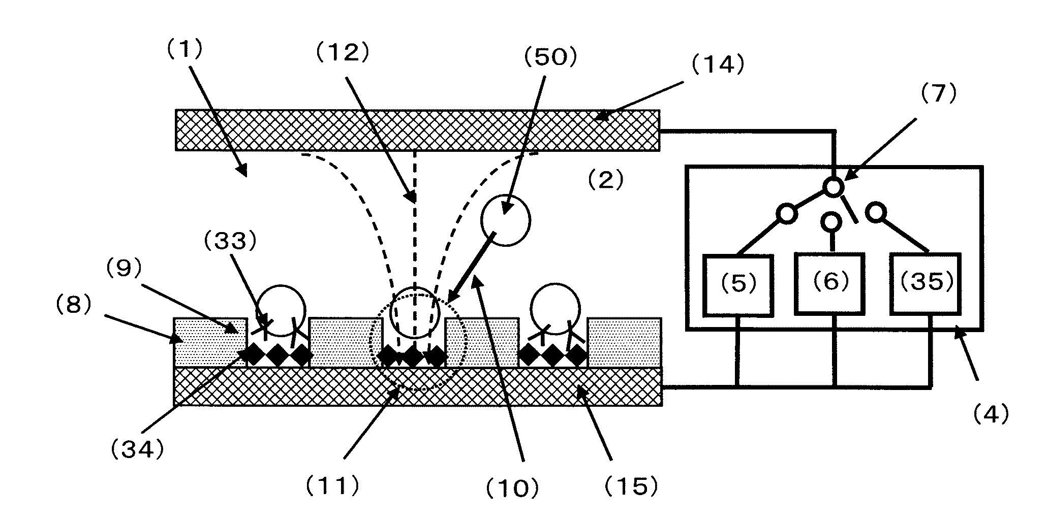
The present invention relates to a cell selection apparatus and method for efficiently selecting cells that produce antibodies that specifically and strongly bind to a foreign matter or disease-related substances. The invention is based on the use of an immunochemical assay method that detects antibodies produced by cells. The technical effect of the invention is to provide a more efficient and accurate method for selecting cells that produce antibodies for use in immunodiagnostic agents and antibody drugs.

Problems solved by technology

However, antibody-producing cells are not able to proliferate when taken out from the organism body, and it is not possible with these cells per se to produce a mass of antibodies on an industrial basis.
Moreover, the number of samples that can be detected all at once is limited to the number of wells per plate.
However, the method described in Patent Document 1 performs the filtration by using a plate having a plurality of wells consisting of wall portions and bottom portions mentioned above, involving a problem in that it is difficult to assay a mass of samples all at once.
However, with this method, sometimes cases arise in which the target cells have to be separated from the magnetic beads bound through the antigen-antibody reaction, involving a problem of complicating its process.
Furthermore, with this method, cells are selected based on whether or not these cells are bound through the antigen-antibody reaction, so it is not possible to select cells based on the strength of the binding force in the antigen-antibody reaction.
However, this method requires an expensive and large-scaled apparatus, involving a problem in that an easy and quick assay is difficult.
Furthermore, with this method, cells are selected based on whether or not these cells are bound through the antigen-antibody reaction, so it is not possible to select cells based on the strength of the binding force in the antigen-antibody reaction.
However, with any one of these methods, the number of cells drastically decreases because the cell selection is carried out before the cell fusion.
Accordingly, since the cell fusion method to be conducted after the cell selection is the PEG method (for example, refer to Non-Patent Document 2 and Non-Patent Document 3) or the electrofusion method (for example, refer to Non-Patent Document 3) which are conventional cell fusion methods, the refusion probability thereof is very low at about 0.2 / 10000 in general, involving a problem in that it is substantially difficult to generate fused cells.
In addition, the operations of the cell selection and the cell fusion are conducted in separate vessels or such separate places, involving a problem in that cells are highly likely to be lost during the replacement of vessels.
However, there is a problem in that the process for separating target cells from collecting cells is complicated.
Furthermore, with this method, cells are selected based on whether or not these cells are bound through the antigen-antibody reaction, so it is not possible to select cells based on the strength of the binding force in the antigen-antibody reaction.

Method used


Image

  • Cell selection apparatus, and cell selection method using the same
  • Cell selection apparatus, and cell selection method using the same
  • Cell selection apparatus, and cell selection method using the same

Examples


example 1

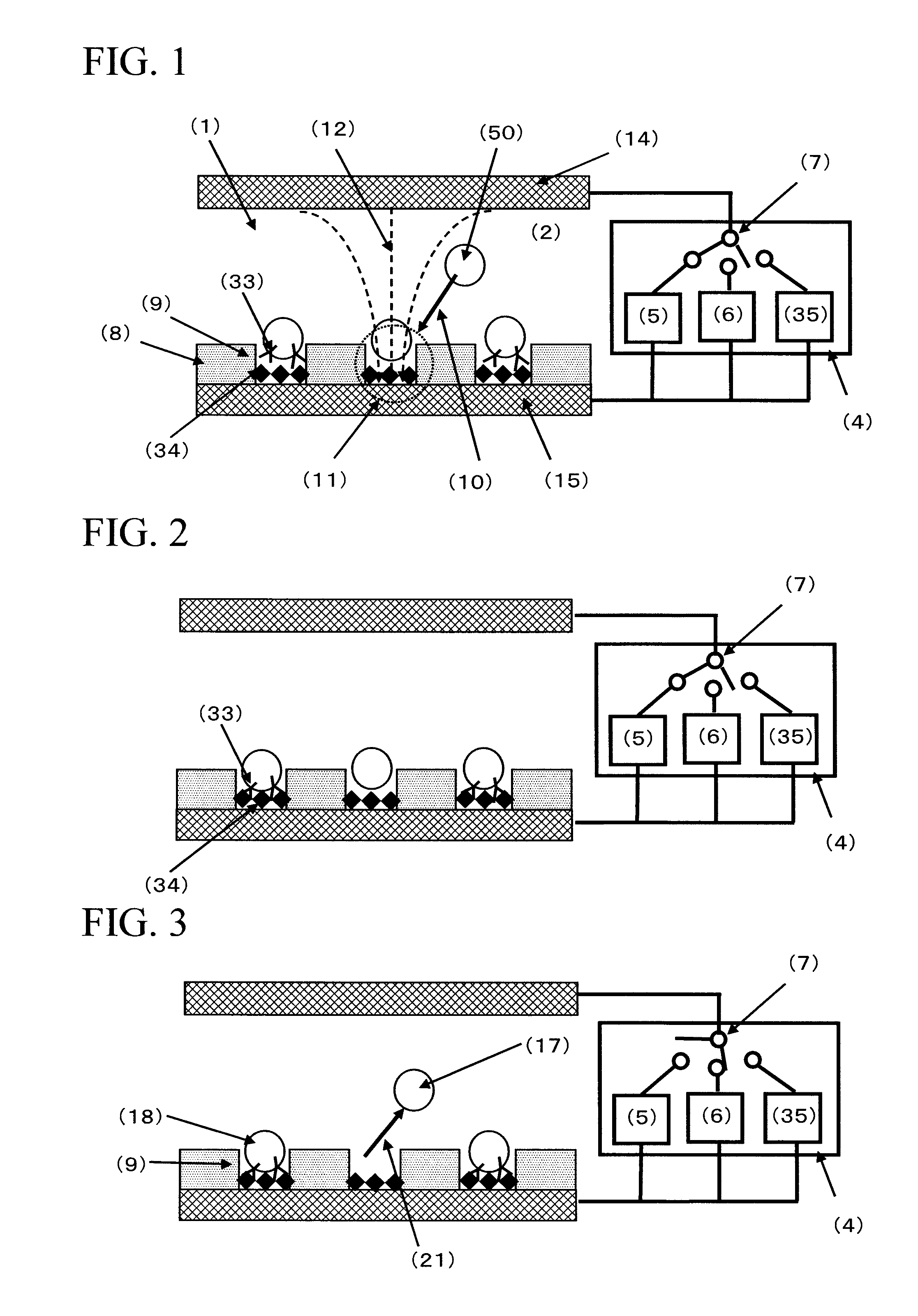
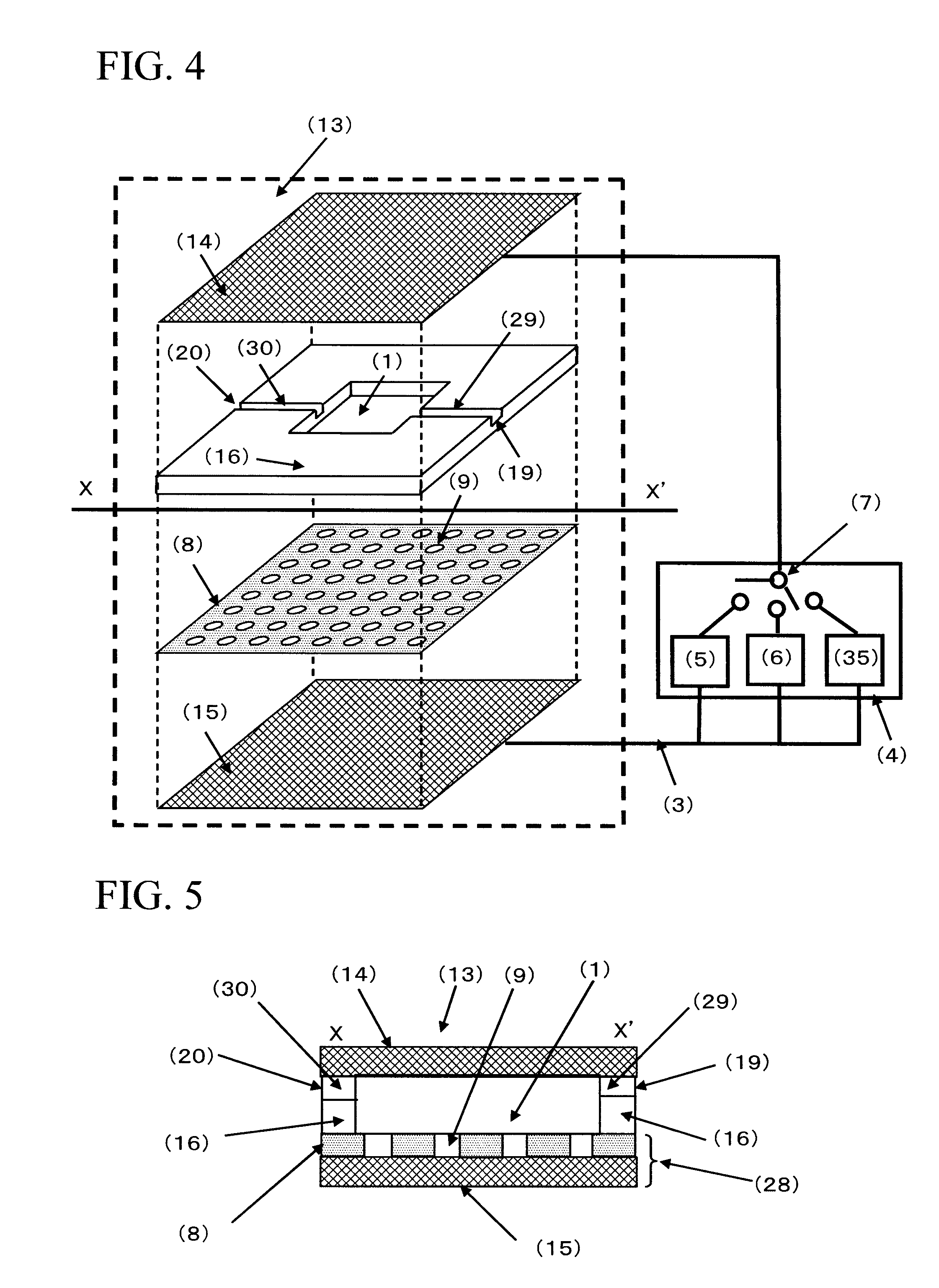
[0172]FIG. 4 is a conceptual diagram of the cell selection apparatus used in Example 1. The cell selection apparatus is roughly composed of a cell selection vessel (13) and a power supply (4). As shown in FIG. 4, the cell selection vessel has a structure in which a spacer (16) is disposed between an upper electrode (14) and a lower electrode (15), and an insulating material (8) having a plurality of micropores formed in an array like arrangement is interposed between the spacer and the lower electrode. As will be described later, the micropores have been formed in the insulating material disposed on the lower electrode (15) by usual photolithography and etching.

[0173]For the upper electrode and the lower electrode, a Pyrex (registered trademark) substrate in a length of 70 mm, a width of 40 mm, and a thickness of 1 mm formed with an ITO film (thickness of 150 nm) was used. For the spacer, a silicone sheet in a length of 40 mm, a width of 40 mm, and a thickness of 1.5 mm in the cente...

example 2

[0189]600 μL of the suspension of the antibody-immobilized polystyrene beads whose surfaces were immobilized with anti-E2 antibodies, made by using the mouse anti-E2 antibody solution at respective concentrations of 0, 0.1, 0.5, and 2.0 μg / mL of Example 1 (bead concentration: about 1.65×10⁶ beads / mL), was respectively introduced from the inlet port of the spacer into the cell selection area by using a 1 mL volume dispenser. Then, by leaving it still for about 5 minutes, the antibody-immobilized polystyrene beads were subjected to gravitational sedimentation. Furthermore, by leaving it still at room temperature for about 40 minutes, the antibody-immobilized polystyrene beads inside the micropores were contacted with the bottom faces of the micropores to effect the antigen-antibody reaction between the antibody on the surface of the antibody-immobilized polystyrene bead and the antigen immobilized on the bottom face of the micropore. Subsequently, an AC voltage of 2.5 Vpp having a fre...

example 3

[0194]Using the same cell selection apparatus of Example 1, spleen cells presenting a specific antibody on their surfaces were selected. Regarding the cells, non-immunized mouse spleen A cells and mouse spleen B cells immunized with an E2 antigen were used. In the mouse spleen B cells immunized with an E2 antigen, there exist cells presenting the E2 antibody on their surfaces (hereunder, referred to as antibody-presenting cells). This Example 3 shows an example in which antibody-presenting cells are selected by identifying the binding force of the antigen-antibody reaction between the antibody presented by this antibody-presenting cell and the antigen immobilized on the bottom face of the micropore, based on the magnitude of the AC voltage of the second AC power supply which defines the strength of the negative dielectrophoretic force.

[0195]First, the mouse spleen A cells and the mouse spleen B cells were respectively suspended in a 300 mM mannitol aqueous solution, and each cell su...


PUM

PropertyMeasurementUnit
AC frequencyaaaaaaaaaa
frequencyaaaaaaaaaa

Abstract

The cell selection apparatus includes: a cell selection vessel which has a pair of electrodes and a sheet-like insulating material having a plurality of micropores, with a recognition molecule bindable to the specific substance being disposed on a bottom face of the micropore; and a power supply, wherein the power supply includes a cell-immobilization power supply and a cell-taking power supply. The cell selection method uses the cell selection apparatus, including; introducing cells into a cell selection area; immobilizing these cells in the micropores; effecting a binding reaction between the specific substance and the recognition molecule; thereafter, taking out a cell of which the specific substance is not or is weakly bound to the recognition molecule, from the micropore; otherwise alternatively, leaving a cell of which the specific substance on the surface of the cell is strongly bound to the recognition molecule, behind in the micropore.

Description

TECHNICAL FIELD[0001]The present invention relates to a cell selection apparatus for efficiently selecting cells, and a cell selection method using the same.[0002]Priority is claimed on Japanese Patent Application No. 2008-105396, filed Apr. 15, 2008, the content of which is incorporated herein by reference.BACKGROUND ART[0003]In recent years, the use of antibodies produced in vivo is attracting an attention as raw materials of diagnostic agents and drugs for diseases. Antibodies are a kind of protein which specifically binds to a foreign matter such as a virus when the foreign matter enters an organism body. An antibody has a function to specifically bind to a specific foreign matter such as a virus to thereby kill or detoxify the virus so as to protect an organism from the invasion of the virus. Here, the foreign matter such as a virus which specifically binds with an antibody is generally called an antigen. Moreover, antibodies in vivo are produced from cells residing in the sple...

Claims


Application Information

Patent Timeline
Patent Type & Authority Applications(United States)
IPC IPC(8): C12N13/00C12M1/42
CPCG01N33/569G01N33/5438
Inventor YAMANAKA, MAHOMARUYAMA, TAKAHIROFUTAMI, TORU
Owner TOSOH CORP
Learn More