Compositions and Methods for Maintenance of Fluid Conducting and Containment Systems

Inactive Publication Date: 2011-02-03
LUX INNOVATE
View PDF20 Cites 25 Cited by
  • Summary
  • Abstract
  • Description
  • Claims
  • Application Information

AI Technical Summary

Benefits of technology

[0040]In a first aspect of the invention, there is provided a composition for treating a system for conduction and containment of fluid, the composition comprising a treatment substance associated with a label, the association between the treatment substance and the label being sufficiently stable that a detectable signal produced due to interaction of the label with a biomacromolecule is representative of the presence of the treatment substance. This composition is ideal for use within industrial and natural systems because it can be easily and conveniently monitored even on-site at off-shore or remote locations by adding a biomacromolecule, and detecting the resulting signal. The user can be sure that any signal that is produced on addition of the biomacromolecule is due to the presence of the composition, firstly because the biomacromolecule has a high specificity for the label and secondly because the biomacromolecule is associated sufficiently with the label. Thus, no signal will be emitted unless the composition is present. A further advantage is that the label is latently detectable. Therefore, no signal will be produced from the sample, even if it contains the composition, until the biomacromolecule is added. In order to detect the signal attributable to the presence of the composition, therefore, a signal measurement can be taken before and after addition of the biomacromolecule, and the former subtracted from the latter. This simple subtraction ensures that any interfering background signal can be easily removed. Sometimes it is necessary to treat the sample to remove background interference such as autofluorescence by addition of chemicals, heat treatment or bleaching. If labels are directly detectable, they may be affected by such treatment and become less detectable, but a latently detectable label on the other hand will advantageously not be affected by such treatment.
[0041]Preferably, the label is attached to the treatment substance. This would provide a particularly stable association between the label and the treatment substance so that the detection of the label can be used as a quantitative indicator of the presence of the treatment substance.
[0042]Preferably, the label is attached to the terminal end of the treatment substance. A label may be attached to each of both terminal ends of a treatment substance. This is beneficial because a detection system that is based on detection of labels will produce results that accurately reflect the true concentration of treatment substance in the system, because the concentration of the label is the same as the concentration of polymeric treatment substance. A label positioned at the end of the polymer may also be of more use for detection or immobilisation purposes, because it will be less likely to be rendered inaccessible to a detection or immobilisation molecule due to coiling of the polymer. A further advantage of this method is that the terminal attachment of the label may also reduce the impact of said label on the function and activity of the polymeric treatment substance molecule.

Problems solved by technology

Fluid conducting and containment systems are susceptible to inefficiencies and loss of productivity due to damage of component parts.
For example, oil and gas operators continue to lose millions of barrels of potential oil production each day due to corrosion, scale and hydrate build up and microbial growth.
The fluid conducting and containment portions of such systems must be continually monitored as many factors can reduce flow efficiency, for example, corrosion of pipes and build up of microbial growth, scale, hydrates, asphaltenes and waxes.
The frequency of chemical interventions is a critical cost factor.
The monitoring process can be labour-intensive and expensive, especially in cases requiring monitoring of treatment substances used in off-shore sites such as oil wells (production wells and injection wells).
For the latter, samples are often flown onshore for testing, which is especially expensive and time consuming.
As fields mature, flights to shore become less frequent, resulting in less comprehensive testing.
Risks of well failure are therefore increased and the need for simple offshore testing grows.
These brine mixtures create a more corrosive environment and, with a greater number of older wells in production, corrosion is an increasing problem.
First, the corrosion inhibitor market is large and there is a tendency to use generic compounds in corrosion inhibitor formulations.
Secondly, corrosion inhibitor residuals are difficult to detect, with no simple test being available particularly for offshore use.
However, detection of corrosion inhibitor residuals remains difficult, particularly offshore.
Finally, the impact of better monitoring on regulations would be positive as the current ‘usage equals discharge’ policy is unlikely to hold true due to complex partitioning behaviours of these chemicals.
Problems may arise with such tests from interferences.
Since they will generate the same signal in fluorometry, colourimetry, ICP-OES etc this is impossible.
However, in samples of produced water from real fields, both methods suffer from a deficiency in that neither method is specific for the polymeric species used in the field.
A problem that is becoming increasingly serious is the lack of adequate methods for the detection of low levels (i.e. minimum inhibitory concentrations MIC) of such treatment substances.
This is particularly the case where the fluid from a large number of wells are joined and flow together along a single flow-line thus presenting problems of co-mingled flow interpretation i.e. determining the concentration of specific chemicals from individual wells.
This issue is common in the deepwater wells of the Gulf of Mexico and West Africa and it is considered that it will be a growing problem in the future as reductions in steel usage leads to more comingling of lines.
Especially considering that, because of the difficulty of reaching these wells each treatment can cost many millions of pounds.
However, fluids used in such systems are frequently highly fluorescent e.g. corrosion inhibitors and oil, and therefore the signal-to-background ratio can be poor, necessitating complicated data processing to measure the concentration of the labelled substance or microbe.
Colourimetry is not always appropriate as a method of detection, for example if it is required that a signal from a coloured or opaque sample such as oil or contaminated water be measured.
The problem with the use of such molecules as labels for treatment substances is that under the extreme conditions encountered within oil and water treatment facilities, amino acid polymer-based molecules are unstable.
In these cases there is no regional distinction to where the labels are appended; they are conjugated to the polymer in a statistical manner via the very same groups that are responsible for the activity and functionality of the polymer giving a high probability that the performance of the treatment chemical will be affected.
There are many problems with such predictions.
As a result, detection of a certain concentration of labels will not necessarily be quantitatively representative of the concentration of molecules of treatment substance.
Furthermore, where the molecular weight of the polymer is lower than 10,000 then the detection of only labeled species will not provide a true representation of the total amount / concentration of labeled and non-labeled chemical.
An example of where this difference in properties would be problematic is when these polymers are applied in an “oilfield squeeze treatment”.
If some polymer molecules have attached more labels than others and the measurements obtained using the detection method are proportional to the amount of label present this could lead to inaccuracies in the analysis; particularly if labeled and non-labeled species have slightly different absorptions to formation rock resulting in staggered return of the different polymer species from the oil well.
As such, where the concentration appears to be lower than in fact it is in reality within the system, the operator will add more treatment chemical and will therefore incur unnecessary costs.
This could have very serious flow assurance consequences affecting oil production such as the blocking up of wells or pipes through scale formation.
Additional problems arise due to the functionality of both the polymeric treatment substance and the functionality of the label.
When the discussed prior art methods are used, the labels will be incorporated throughout the length of the polymers, since it is not possible to control the location of label incorporation.
As a result, the labels may be less detectable or may be less useful for immobilization purposes especially where the label has properties that allow it to be used to extract the entire polymer from a mixture, because polymers can coil, obscuring the label and preventing access to detection molecules or immobilization surfaces.
In such a case, even labeled polymer could go undetected, because the detection molecule is obstructed from interacting with the label.
In addition, the more labels that are present on the polymer, the greater the chance that their presence will affect the properties / function of the polymer.
For example, the efficacy of the treatment polymer could be reduced with the result that its minimum inhibitory concentration (MIC) is higher such that a greater amount of treatment substance will be required to provide the same protection to the wells and pipes thus increasing costs.
Another cost related issue is that by their vary nature these labels can be relatively expensive compared to the cost of the monomers used to make treatment chemical polymers so it would be more cost effective to have as little label as possible present.
Unfortunately, it can be difficult to achieve the attachment of a minimal amount of label to a polymer by statistical means.
However, attempts to do this can result in a large proportion of non-labeled polymer in a sample.

Method used


Image

  • Compositions and Methods for Maintenance of Fluid Conducting and Containment Systems
  • Compositions and Methods for Maintenance of Fluid Conducting and Containment Systems
  • Compositions and Methods for Maintenance of Fluid Conducting and Containment Systems

Examples


example 1

Coupling of Biotin to a Polymeric Scale Inhibitor

[0126]In order to produce a treatment composition comprising a label and treatment substance according to the invention, the coupling of biotin to a polymeric scale inhibitor was investigated. In one example, an amide bond is formed between biotin ethylenediamine and carboxylic acid-containing polymeric scale inhibitor, using EDC chemistries. This reaction may be performed by those skilled in the art. 1-Ethyl-3-[3-dimethylaminopropyl]carbodiimide hydrochloride (EDC or EDC) is the main water-soluble carbodiimide available and is used to couple carboxyl groups to primary amines. EDC reacts with a carboxyl to form an amine-reactive O-acylisourea intermediate. In the presence of biotin ethylenediamine an amide bond is formed between the carboxylic acid-containing treatment chemical and biotin label. NHS (defined below) is added to stabilize the intermediate increasing the efficiency of the coupling. The small molecule marker used was biot...

example 2

Scale Inhibiting Activity of Labeled Scale Inhibitors

[0164]The scale-inhibitor activity of labeled scale inhibitors was determined using static bottle tests (barite). This test is used to assess how efficient the chemicals are at inhibiting scale build-up compared with the unlabeled original chemicals. Inhibitors, labeled or unlabeled, were analysed in duplicate in 50:50 Forties Formation Water: Seawater at 95° C., tested after a 22-hour incubation. Solutions are dosed with inhibitor and incubated. Undosed solutions serve to provide a ‘base-line’ scaling potential of the water system. After incubation, the aliquots are sampled and the concentration of the scaling cations of interest in each sample is determined by ICP-OES (inductively coupled plasma-optical emission spectrometer). This analysis method is known by the one skilled in the art of detecting, identifying and / or quantifying single chemical elements. Results from one such test are shown in FIG. 3. They indicate that decreas...

example 3

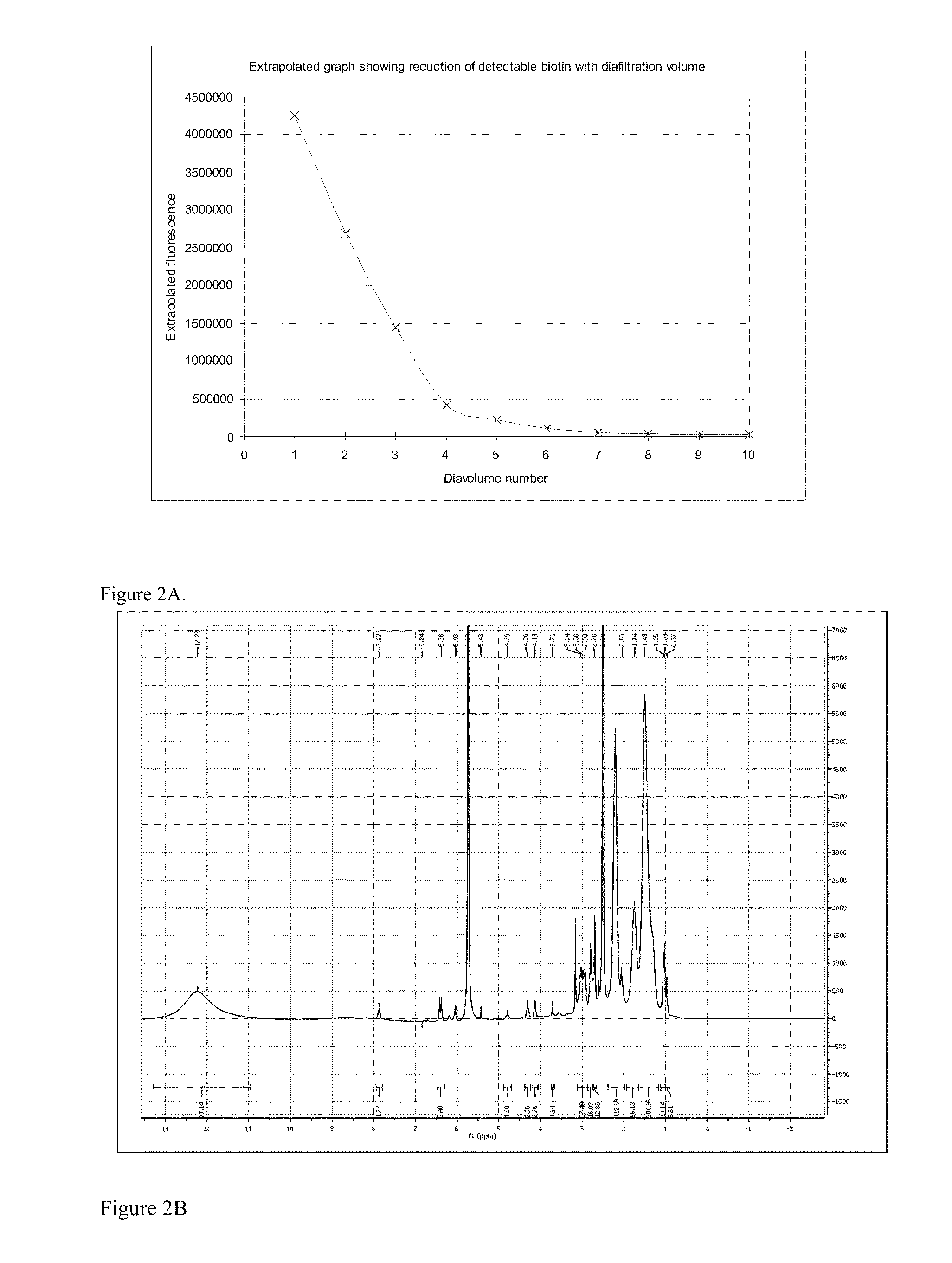
Limits of Detection of an Exemplary Labelling Molecule

[0165]Where the label in question is added during production of the treatment substance, for example during copolymerisation of polymeric scale inhibitors, more label molecules may be incorporated if it is desired to increase the detectability of the conjugate on addition of the associated biomacromolecule. Conversely, if the signal created on addition of the biomacromolecule is excessive and difficult to measure, the amount of label may be reduced. The limits of detection of the labels range from a concentration of 1 part per billion to parts per million. For treatment substance-label conjugates to be useful they need to be able to be detected at very low levels. Continuously injected scale inhibitors are typically loaded into the wells at 5-500 ppm. For squeeze treatments, the inhibitors may be resqueezed when the inhibitor reaches 1 ppm. Therefore, the limit of detection of modified treatment substances will ideally be below 1...


PUM


Abstract

Latently detectable small molecules, or ‘labels’, used for monitoring of treatment substances in fluid conducting and containment systems. A composition comprising the treatment substance and the label, a method of manufacturing the composition, a method and kit for use in monitoring the treatment substances in a fluid conducting and containment system, and a method for treating such a system using the composition are also disclosed.

Description

FIELD OF THE INVENTION[0001]This invention relates to latently detectable small molecules, or ‘labels’, used for monitoring of treatment substances in fluid conducting and containment systems. More specifically, the invention relates to a composition comprising the treatment substance and the label, a method of manufacturing the composition, a method and kit for use in monitoring the treatment substances in a fluid conducting and containment system, and a method for treating such a system using the composition.BACKGROUND OF THE INVENTION[0002]Fluid conducting and containment systems are susceptible to inefficiencies and loss of productivity due to damage of component parts. For example, oil and gas operators continue to lose millions of barrels of potential oil production each day due to corrosion, scale and hydrate build up and microbial growth. Systems include, for example, oil and gas reservoirs and their associated infrastructure (wells, pipelines, separation facilities etc), pe...

Claims


Application Information

Patent Timeline
IPC IPC(8): G01N33/53G01N21/00
CPCC08F2/005
Inventor MOUSSAVI, ARTINROWLEY-WILLIAMS, CATHERINEMACKENZIE, CAMERONMACKAY, FIONAFULLER, ANNE-MARIEMAGDALENIC, VJERAPERFECT, EMMA
Owner LUX INNOVATE
Why Eureka
Try Eureka