
Circuit Arrangement For A Motor Vehicle Data Bus

Inactive Publication Date: 2011-01-27
CONTINENTAL TEVES AG & CO OHG
View PDF15 Cites 21 Cited by
  • Summary
  • Abstract
  • Description
  • Claims
  • Application Information

AI Technical Summary

Benefits of technology

[0009]An object of the present invention is now to specify a transmission and / or reception circuit for the physical implementation of a motor vehicle data bus which is flexibly configurable and of simple design.
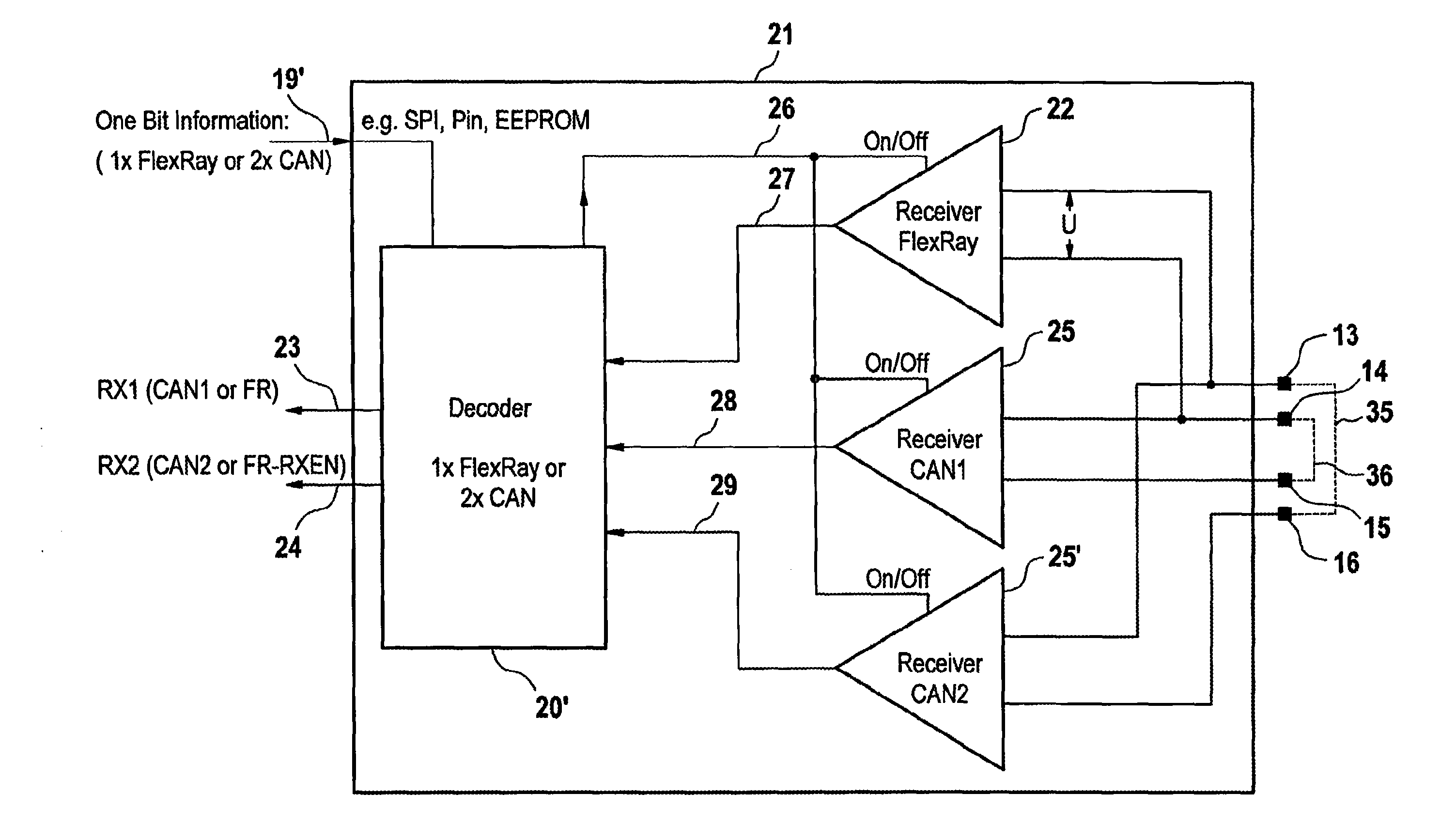
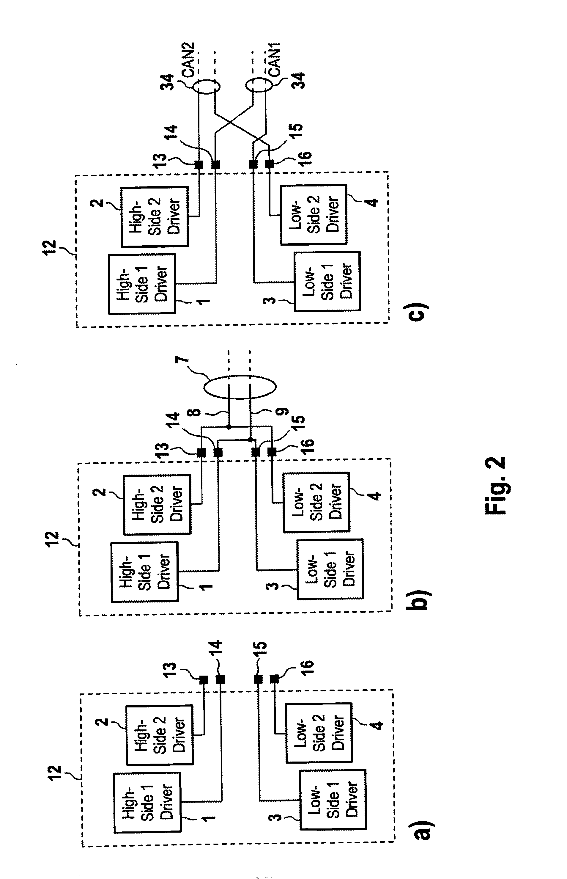
[0010]In at least one aspect, the invention addresses the following problem: in order to be universally usable, controllers must frequently provide both a CAN bus connection and a FlexRay(R) connection. An inherently known FlexRay transceiver is usually larger and therefore more expensive than a CAN transceiver. The invention contains the idea that partially combining circuit elements from the two conventional CAN transceivers provides the opportunity to use the transceiver formed for a plurality of bus types, that is to say particularly CAN and FlexRay. Furthermore, one exemplary embodiment makes it possible to change between a FlexRay connection and two CAN connections.
[0016]In a controller which already has two or more CAN connections (and appropriate electronic transceiver elements therefore), it may be advantageous to provide a FlexRay connection instead of a CAN connection (or else both CAN connections). Since the transceiver electronics which belong to this FlexRay connection can also be operated as a CanBus, as shown above, this uses up less chip area, particularly when implemented on an integrated chip. This results in significant cost advantages for production in large quantities. The inventive driver or reception circuit is therefore particularly suitable for use as part of a user-specific circuit (ASIC), which is preferred, since normally these are produced in large quantities, which means that component savings are advantageous for economic reasons. An additional effect advantageously achieved is that pin compatibility between CAN mode and FlexRay(R) mode exists for the bus connections and the logic inputs and outputs.

Problems solved by technology

An inherently known FlexRay transceiver is usually larger and therefore more expensive than a CAN transceiver.

Method used


Image

  • Circuit Arrangement For A Motor Vehicle Data Bus
  • Circuit Arrangement For A Motor Vehicle Data Bus
  • Circuit Arrangement For A Motor Vehicle Data Bus

Examples


Embodiment Construction

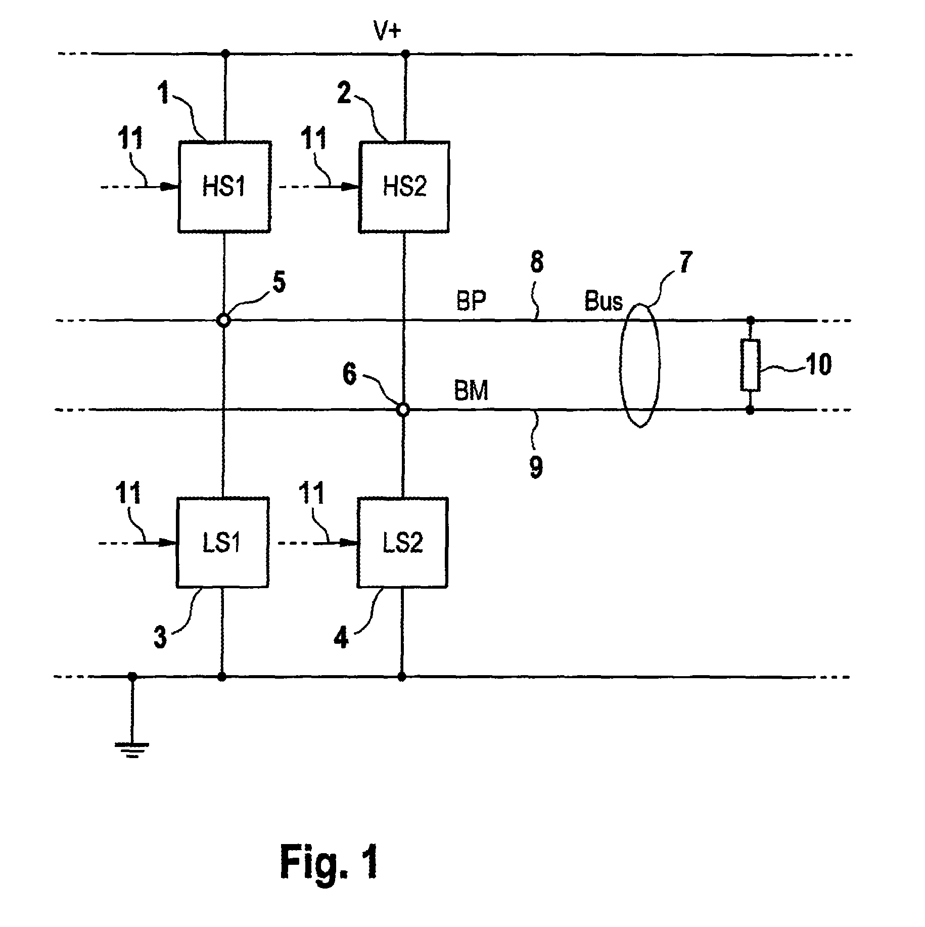
[0024]In FIG. 1, the drivers 1 . . . 4 (HS1, HS2, LS1, LS2) form a network node which is connected by means of terminals 5 and 6 to data bus 7. Bus 7 comprises the bus lines 8 (BP) and 9 (BM) of a FlexRay(R) network. Bus 7 has further bus subscribers, e.g. receiver nodes—not shown—or a bus termination 10, connected to it. Control lines 11 can be used by control electronics—not shown—to actuate the drivers 1 . . . 4. Suitable actuation of the drivers 1 . . . 4 allows a defined flow of current from node 5 to node 6 (or in the opposite direction) to be set. On the basis of the FlexRay(R) specification, the current direction determines the binary state “1” or “0” for a data bit which is to be transmitted via the bus. In the “1” state, a current flows from high-side driver 1 via line 8 to termination 10 (or to the receiver). From there, the current flows back via line 9 to low-side driver 4. When the “0” state is transmitted, the current flows from high-side driver 2 via line 9 to termin...


PUM


Abstract

Transmission and / or reception circuit arrangement for the physical implementation of a motor vehicle data bus system and use thereof, wherein the circuit has a plurality of configurable modes of operation which are a different physical implementation of one or more logic states and also comprises electronic bit generation and / or bit reception circuit elements which are used in each mode of operation, wherein changeover and / or structure elements are present which can be used to change over the circuit arrangement between the modes of operation and / or to operate said circuit arrangement in different modes of operation.

Description

CROSS REFERENCE TO RELATED APPLICATIONS[0001]This application is the U.S. national phase application of PCT International Application No. PCT / EP2008 / 050379, filed Jan. 15, 2008, which claims priority to German Patent Application No. DE 102007003326.7, filed Jan. 17, 2007 and German Patent Application No. DE 102008004551.9, filed Jan. 15, 2008,the contents of such applications being incorporated by reference herein.BACKGROUND OF THE INVENTION[0002]1. Field of the Invention[0003]The invention relates to a transmission and / or reception circuit arrangement for the physical implementation of a motor vehicle data bus system and the use thereof in a motor vehicle controller.[0004]2. Description of the Related Art[0005]FlexRay(R) is a bus standard for electronic controllers in motor vehicles which is intended to allow particularly rapid, realtime-compatible and error-tolerant transmission of the data. FlexRay(R) is regarded by many leading motor vehicle manufacturers and their suppliers as ...

Claims


Application Information

Patent Timeline
IPC IPC(8): G06F13/40
CPCH04L12/40032H04L12/40169H04L2012/40273H04L2012/40241H04L2012/40215H04L12/40
Inventor BECKMANN, TOBIASBUCHLER, ROMANFEY, WOFGANG
Owner CONTINENTAL TEVES AG & CO OHG
Learn More