
Low voltage driver for high voltage LCD

a low voltage, high-voltage technology, applied in the direction of electric digital data processing, instruments, computing, etc., can solve the problem that the rms voltage might not be enough for proper contrast, and achieve the effect of less power, less chip area, and less expensiv

Active Publication Date: 2008-04-03
ANALOG DEVICES INC
View PDF12 Cites 1 Cited by
  • Summary
  • Abstract
  • Description
  • Claims
  • Application Information

AI Technical Summary

Benefits of technology

[0006] It is a further object of this invention to provide such a low voltage driver for a higher voltage LCD which is less expensive, and requires less chip area and less power.

Problems solved by technology

For CMOS processes with feature size less than 0.25 μm, 5V tolerant devices are not available for normal digital processes, and one would have to avail of the expensive 5V tolerant option to drive these panels.
Since the required RMS voltage, for reasonable contrast, increases with decreasing temperature, even for 3-3.6V LCD panels the RMS voltage might not be enough for proper contrast at cold temperatures, if driven from a 3.6V supply.

Method used


Image

  • Low voltage driver for high voltage LCD
  • Low voltage driver for high voltage LCD
  • Low voltage driver for high voltage LCD

Examples


Embodiment Construction

[0018] Aside from the preferred embodiment or embodiments disclosed below, this invention is capable of other embodiments and of being practiced or being carried out in various ways. Thus, it is to be understood that the invention is not limited in its application to the details of construction and the arrangements of components set forth in the following description or illustrated in the drawings. If only one embodiment is described herein, the claims hereof are not to be limited to that embodiment. Moreover, the claims hereof are not to be read restrictively unless there is clear and convincing evidence manifesting a certain exclusion, restriction, or disclaimer.

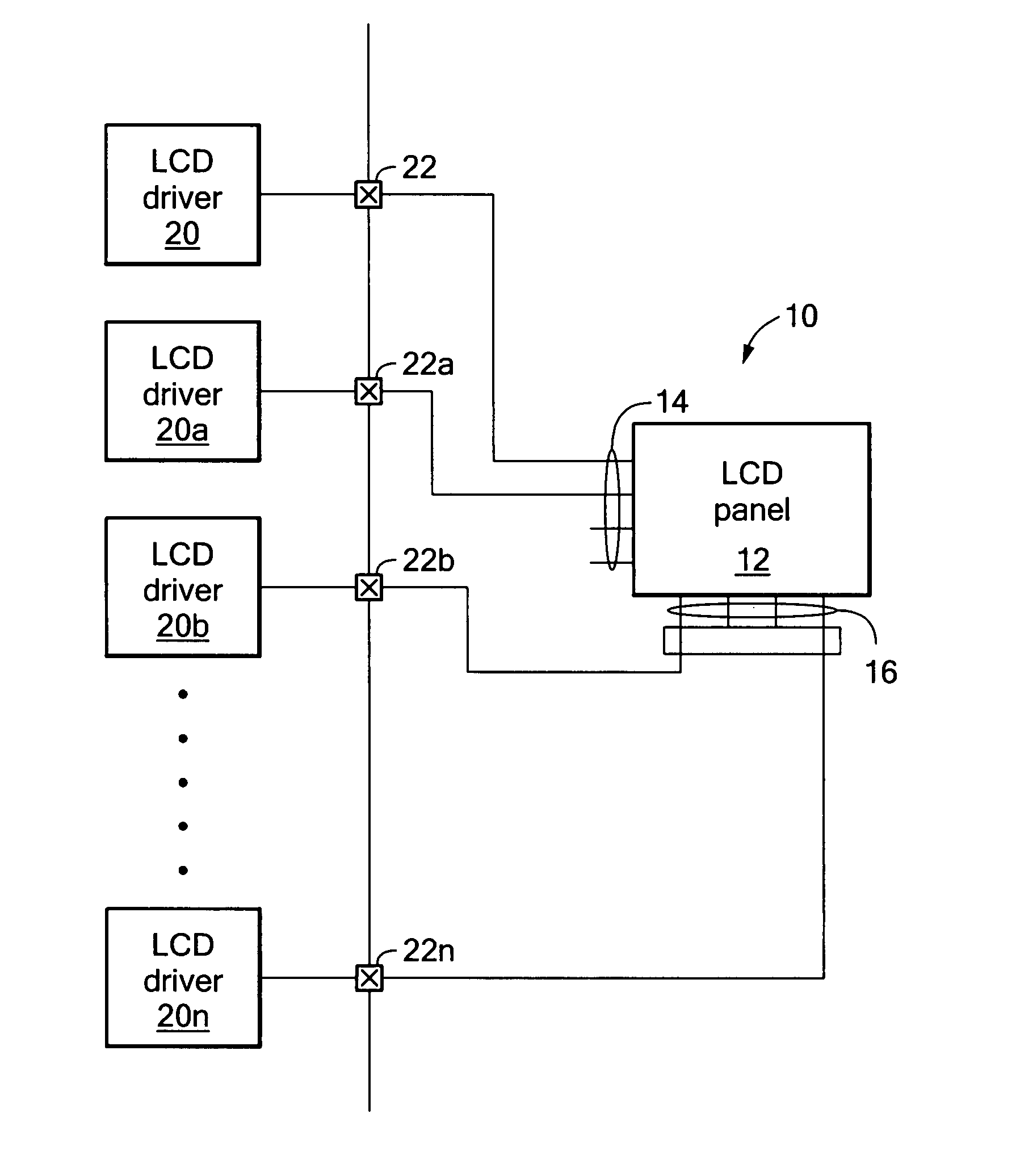
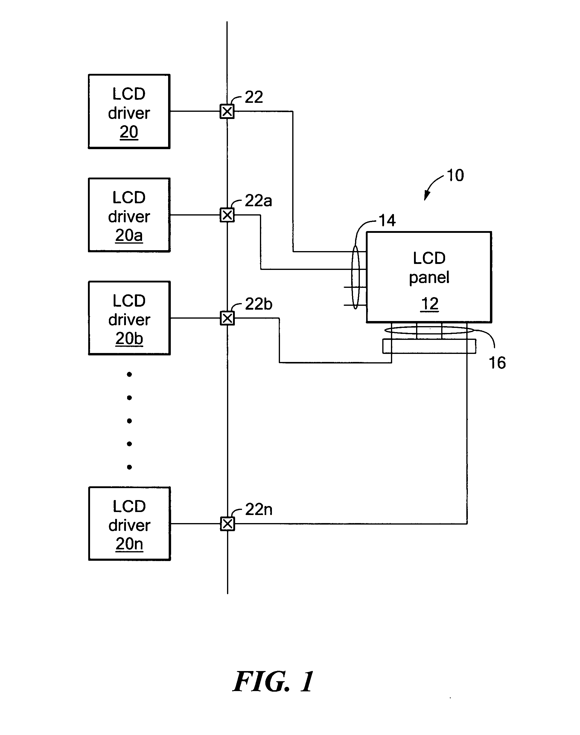
[0019] There is shown in FIG. 1 an LCD 10 including LCD panel 12 with common contacts 14 and segment contacts 16 and a number of LCD drivers 20, 20a, 20b . . . 20n, each of which provides a drive signal on its associated output 22, 22a, 22b . . . 22n to a one of the common contacts 14 and segment contacts 16.

[0020] Each ...


PUM


Abstract

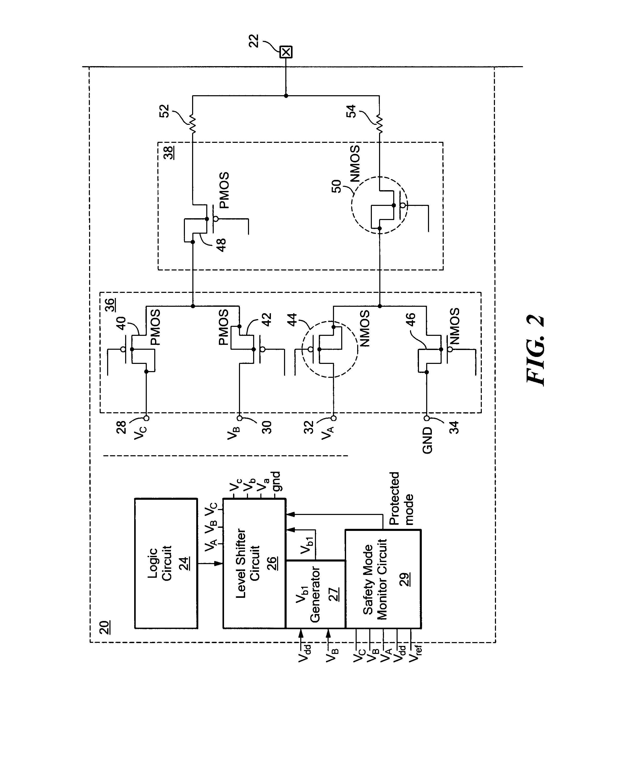
A low voltage driver for a higher voltage LCD includes a plurality of LCD drive bias voltage input-terminals; an LCD drive voltage output terminal; an input transistor switching circuit having at least one switch for each LCD drive bias voltage for selecting one of the bias voltages; an output transistor switching circuit, responsive to the input transistor switching circuit, for applying the selected one of the bias voltages to the LCD drive voltage output terminal, the transistors of the switching circuits having a predetermined breakdown voltage; a level shifter for providing switching voltages counterpart to the plurality of bias voltages; a logic circuit for enabling the first transistor switching circuit to select a one of the bias voltages and applying a set of counterpart switching voltages to the input and output transistor switching circuits for connecting the selected one of the bias voltages to the output terminal and applying a set of switching voltages to the input and output switching circuits which limit the voltage across the transistor junctions in the switching circuit to less than the predetermined breakdown voltage.

Description

RELATED APPLICATIONS [0001] This application claims benefit of and priority to U.S. Provisional Application Ser. No. 60 / 848,908 filed Oct. 3, 2006 incorporated herein by this reference.FIELD OF THE INVENTION [0002] This invention relates to a low voltage driver for a high voltage LCD. BACKGROUND OF THE INVENTION [0003] Twisted Nematic (TN) type or Super Twisted Nematic (STN) type liquid crystal displays (LCDs) are the types of displays used in watches and other common low cost monochromatic displays like energy meters. These displays are described as root mean square (RMS) responsive meaning the behavior is a function of the RMS voltage applied. The fundamental affect on the light is to rotate polarized light as it passes through the liquid crystal fluid. The amount of twist is controlled by the RMS voltage applied For twisted nematic LCDs the driver a.c. segment waveforms are constructed by predetermined timed combinations of voltage levels of e.g. half bias GND: ½:1 or one third b...

Claims


Application Information

Patent Timeline
Patent Type & Authority Applications(United States)
IPC IPC(8): G09G5/00
CPCG09G3/3681G09G3/3692G09G2310/0289G09G3/3696G09G2330/04G09G3/3233G09G2330/02
Inventor BANDYOPADHYAY, ABHISHEKNESTLER, ERICASHBURN, MICHAEL A. JR.
Owner ANALOG DEVICES INC
Learn More