Control logic method and system for optimizing natural gas production

Inactive Publication Date: 2011-01-06
OPTIMUM PROD TECH INC
View PDF8 Cites 19 Cited by
  • Summary
  • Abstract
  • Description
  • Claims
  • Application Information

AI Technical Summary

Benefits of technology

[0060]It will be apparent to persons skilled in the art that the system of the invention can be readily adapted to regulate more than separate fluid flows originating from a single fluid flow source, by using additional control valves as appropriate in accordance with the concepts described herein.
[0113]In a first embodiment, the control valve assembly also comprises an upstream bypass line connecting the fluid inlet and the pressure source; an upstream solenoid operable to regulate fluid flow through the upstream bypass line; a downstream bypass line connecting the fluid outlet and the pressure source; and a downstream solenoid operable to regulate fluid flow through the downstream bypass line. When the pressure at the fluid inlet is greater than the pressure source pressure, opening the upstream solenoid will increase the pressure source pressure. When the pressure at the fluid outlet is less than the pressure source pressure, opening the downstream solenoid will decrease the pressure source pressure.
[0116]a sufficient increase in the pressure source pressure will deform the bladder into contact against the conical sidewalls of the valve core sections so as to restrict fluid flow through one or more perforations, thereby reducing the fluid flow rate through the valve;
[0119]In control valve assemblies in accordance with the present invention, one or both of the upstream and downstream solenoids optionally may be adapted for pulsed operation, thereby facilitating incremental adjustments to the pressure source pressure.

Problems solved by technology

Typically these wells will flow with excess velocity (i.e., significantly greater than VCR), resulting in friction between the flowing fluids and the production chamber.
Lower fluid velocity provides the benefit of reduced friction loading; however, it also diminishes the water-lifting capability of the wellbore.
This accumulation of liquids results in increased bottomhole flowing pressures and reduced gas recoveries.
Friction loading is caused by fluid flowing up the production tubing at high velocity, and results in restricted formation drawdown.
Friction loading typically will not “kill” a well (i.e., completely halt the production of well fluids); however, it can significantly restrict production.
Liquid loading is caused by insufficient fluid velocity up the production tubing.
Like friction loading, liquid loading results in restricted formation drawdown.
Liquid loading will eventually result in the well being killed.
Any time a wellbore is “killed” (i.e., its production of well fluids is stopped) due to excessive liquids, considerable costs must be incurred to correct the problem and restore production from the well.
However, increased flow velocity also promotes increased friction loading.
If such a leak occurs, there would merely be a harmless transfer of gas from the positive pressure jacket into the intake pipeline.
Should a leak develop in the positive pressure jacket, gas therefrom will escape into the atmosphere, and entry of air into the positive pressure jacket will be impossible.
Due to this narrow capacity range and the inherent complexity of the control valve, maintenance and design must be done by professional instrumentation personnel.
As a result, conventional control valves are relatively expensive to purchase and maintain.
Most if not all control valves commonly used in the natural gas industry are pneumatically driven, and their operation typically results in the venting of methane gas to the atmosphere.
In the past, this undesirable operational characteristic was considered tolerable in view of the reliability of such pneumatically-actuated control valves.
However, electric actuators are comparatively expensive and have significant electrical power requirements, with correspondingly high operating costs.
At lower external fluid pressures, the bladder will restrict but not completely prevent fluid flow through the valve.

Method used


Image

  • Control logic method and system for optimizing natural gas production
  • Control logic method and system for optimizing natural gas production
  • Control logic method and system for optimizing natural gas production

Examples


Embodiment Construction

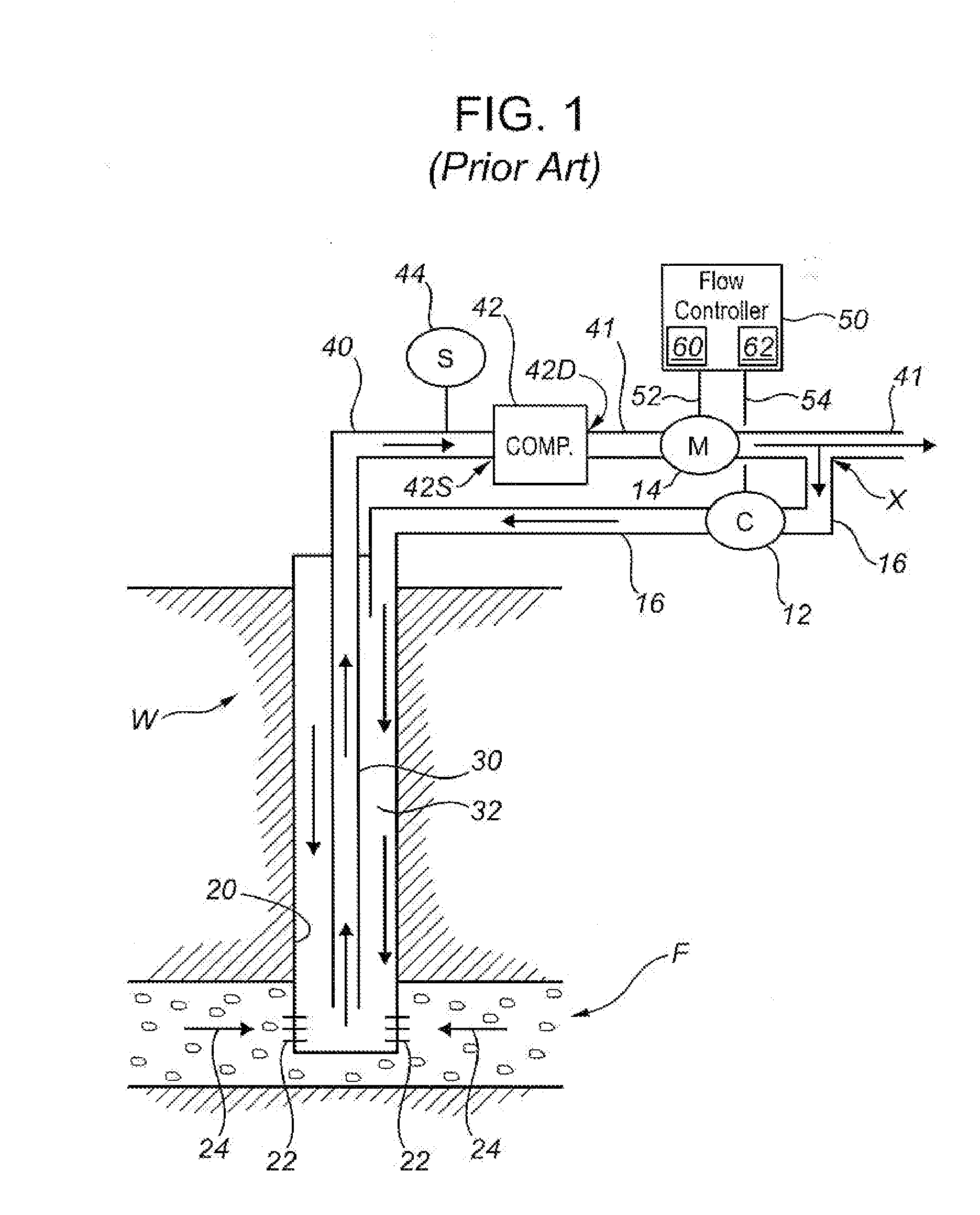
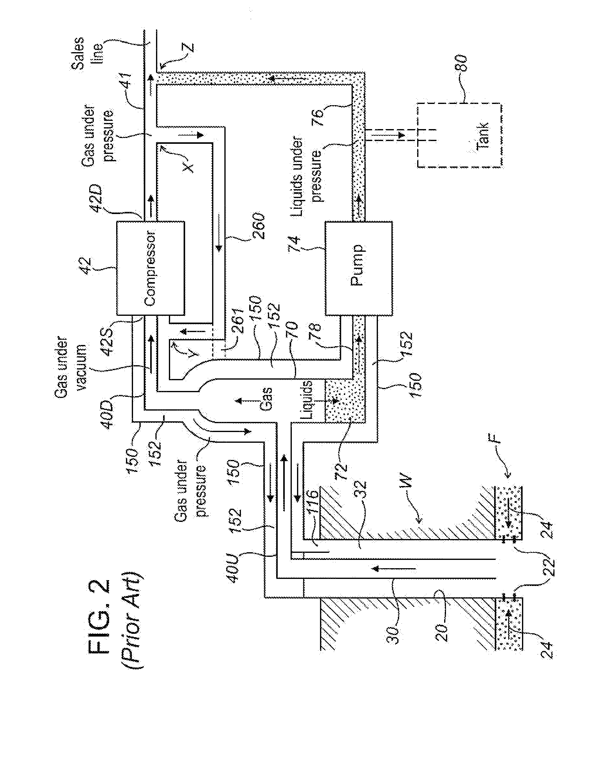
[0136]The teachings of the present invention may be best understood after first reviewing methods and apparatus taught by the previously-mentioned U.S. Pat. No. 6,991,034 and No. 7,275,599 (the entire disclosures of which are incorporated herein by reference).

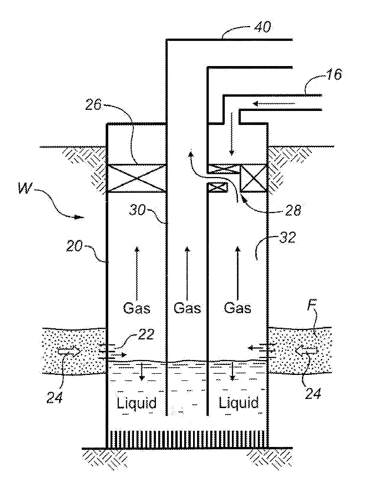
[0137]FIG. 1 schematically illustrates a natural gas well W penetrating a subsurface formation F containing natural gas, with well W producing gas under velocity-induced flow conditions in accordance with one embodiment of the methods taught in U.S. Pat. No. 6,991,034. Well W is lined with a casing 20 which has a number of perforations conceptually illustrated by short lines 22 within a production zone (generally corresponding to the portion of the well penetrating the formation F). As conceptually indicated by arrows 24, formation fluids including gas, oil, and water flow into the well through perforations 22. A string of tubing 30 extends inside casing 20, terminating at a point within the production zone. The bottom end of t...


PUM


Abstract

In a system for optimizing natural gas production in response to real-time variations in wellbore parameters, a PLC or other wellsite intelligence technology is used to monitor liquid and gas production from the wellbore under friction-loaded conditions. Using baseline production data obtained during production tests, the PLC determines and initiates the appropriate operating mode for the wellbore to optimize a selected production criterion to suit measured wellbore parameters. The operating mode either a continuous clean-out mode, in which gas is continuously injected into the wellbore to control liquid loading, or an intermittent clean-out, in which liquid loading is regulated by intermittent gas injection. In preferred embodiments, the system uses bladder-type control valves having upstream and downstream solenoids, to control production tubing flow rate within a range between upper and lower set points.

Description

CROSS-REFERENCE TO RELATED APPLICATIONS[0001]This application is a continuation-in-part (CIP) of International Application No. PCT / CA2010 / 000319, which designates the United States, has an international filing date of Mar. 4, 2010, and is pending as of the filing date of the present CIP application. PCT / CA2010 / 000319 claims the benefit of U.S. Patent Application No. 61 / 157,300, filed Mar. 4, 2009, and further claims the benefit of U.S. Patent Application No. 61 / 229,673, filed Jul. 29, 2009. All three said earlier applications are incorporated herein by reference in their entirety for continuity of disclosure.FIELD OF THE INVENTION[0002]The present invention relates to methods and apparatus for optimizing production in natural gas wells, particularly in gas wells producing with fixed-velocity lift systems. The present invention further relates to flow control valves adaptable for use in conjunction with gas well production optimization methods and systems, particularly including flow...

Claims


Application Information

Patent Timeline
IPC IPC(8): E21B34/08G05D7/06
CPCE21B34/06E21B43/12F16K31/42F16K7/075E21B44/00
Inventor WILDE, GLENNJONK, DENNIS
Owner OPTIMUM PROD TECH INC
Why Eureka
Try Eureka