
Method for forming holograms

a reflection hologram and hologram technology, applied in the field of reflection holograms, can solve the problems of not allowing for distinguishing the difficulty of recording and reading on the optical recording medium, and the inability to describe the magnitude and shape of the plane wave, etc., to achieve good recording and reading operations and high-density recording

Inactive Publication Date: 2011-01-06
TDK CORPARATION
View PDF2 Cites 0 Cited by
  • Summary
  • Abstract
  • Description
  • Claims
  • Application Information

AI Technical Summary

Benefits of technology

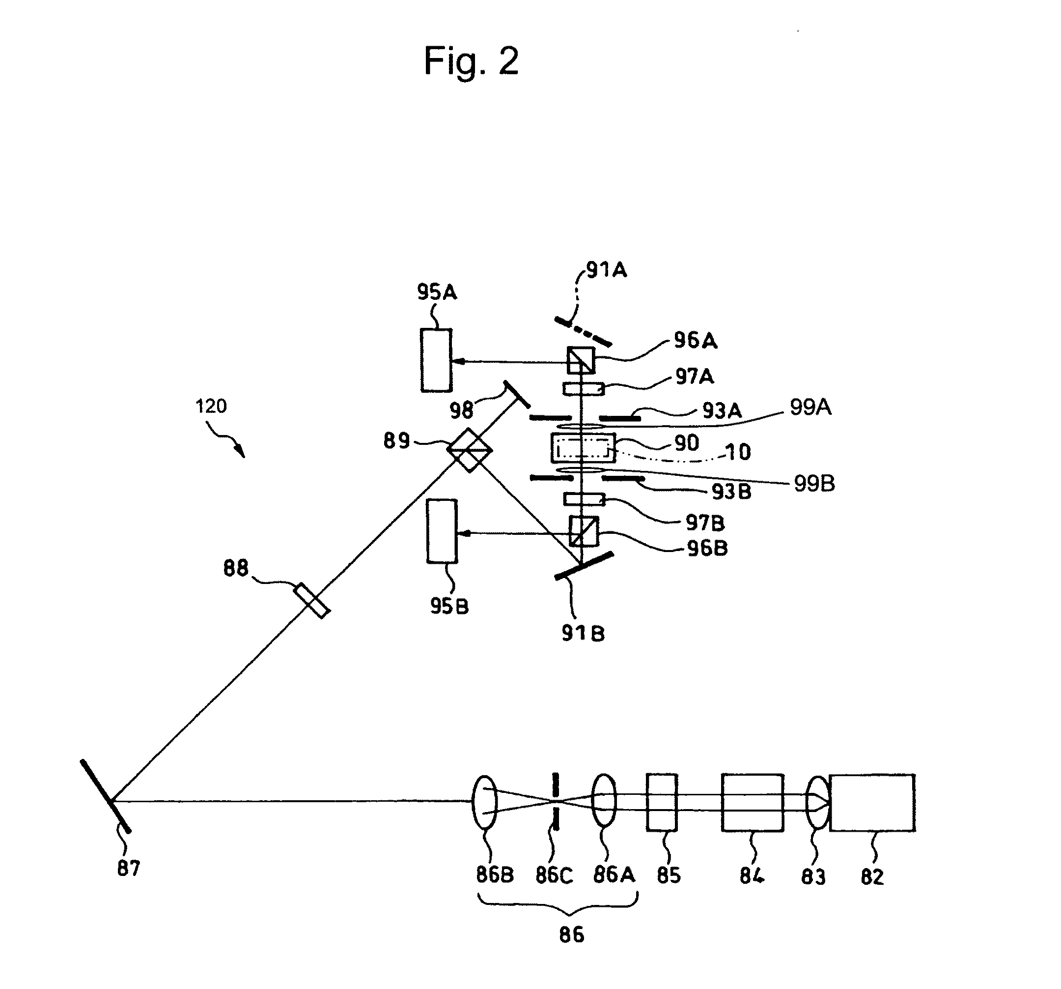
The present invention provides a method for forming reflection holograms on an optical recording medium to create a recording medium with uniform reflectivity. This method involves focusing a laser beam through an objective lens and allowing it to interfere with a second beam within the medium. The laser beam is designed to meet certain conditions, such as d / 2≦4λn / (NA)2, where d is the thickness of the information recording layer). This method allows for good recording and reading operations and high-density recording.

Problems solved by technology

However, the publication made no description to the magnitude and shape of the plane waves.
Accordingly, alteration recording by focusing a laser beam on such a reflection hologram, which has a significant variation in the reflected beam, does not allow for distinguishing oscillations of the hologram itself from the variation resulting from the alteration recording.
This would thus make recording and reading on the optical recording medium substantially difficult to implement.

Method used


Image

  • Method for forming holograms
  • Method for forming holograms
  • Method for forming holograms

Examples


first embodiment

[0048]The disc-shaped optical recording medium 10 with a hologram formed was manufactured as follows.

(Manufacturing of Medium)

[0049]7.3 g of tetrabutoxy titanium (Ti(OBu)4, manufactured by Kojundo Chemical Laboratory Co., Ltd.) and 5.04 g of 2-ethylpentane-2,4-diol (manufactured by Tokyo Chemical Industry Co., Ltd.) were mixed in 2 ml of an n-buthanol solvent at room temperature and stirred for ten minutes. At that time, the mole ratio was Ti(OBu)4:2-methylpentane-2,4-diol=1:2.

[0050]This reaction solution was mixed with 5.2 g of diphenyldimethoxysilane (PH2Si(OMe)2 manufactured by Shin-Etsu Chemical Co., Ltd.) into a metal alkoxide solution. At that time, the mole ratio was Ti:Si=1:1.

[0051]Next, a solution made up of 0.4 ml of water, 0.16 ml of 2N hydrochloric acid, and 2 ml of solvent ethanol was added dropwise at room temperature into the metal alkoxide solution while being stirred. The stirring continued for 30 minutes to cause hydrolysis reaction and condensation reaction, there...


PUM

PropertyMeasurementUnit
wavelengthaaaaaaaaaa
refractive indexaaaaaaaaaa
thicknessaaaaaaaaaa

Abstract

A reflection type hologram recording optical system is provided which implements a method for forming a light reflection hologram having uniform reflectivity. The method includes: focusing a first laser beam through one of a pair of objective lenses, the first beam satisfying the condition given by, 4λn / (NA)2<D, where λ (μm) is the wavelength of the first laser beam, NA is the numerical aperture of the pair of objective lenses, n is the average refractive index of the optical recording medium, and D (μm) is the thickness of the medium; allowing the first laser beam to interfere with a second laser beam within the optical recording medium, the second laser beam being focused through the other opposing objective lens; and allowing the optical recording medium and a flux of the laser beams to be displaced relative to each other, thereby forming a light reflection hologram having uniform reflectivity.

Description

BACKGROUND OF THE INVENTION[0001]1. Field of the Invention[0002]The present invention relates to a method for forming reflection holograms on an information recording layer of an optical recording medium.[0003]2. Description of the Related Art[0004]A device or a holographic recording medium for writing holograms thereon is disclosed in Japanese Translation of PCT Patent Application No. 2002-502057. The medium has a reflection format hologram formed therein and data written as localized alteration within the format hologram.[0005]The recording medium disclosed in Japanese Translation of PCT. Patent Application No. 2002-502057 describes that the reflection format hologram extending across the entire volume of the recording medium is formed by two opposing plane waves which are perpendicular to the direction of depth of the recording medium and have a substantially flat peripheral portion. However, the publication made no description to the magnitude and shape of the plane waves.[0006]...

Claims


Application Information

Patent Timeline
Patent Type & Authority Applications(United States)
IPC IPC(8): G03F7/00
CPCG03F7/001G03F7/0043G03H1/28G03H1/30G11B7/00772G03H2001/2655G03H2222/54G03H2227/03G11B7/0065G03H2001/0415
Inventor YOSHINARI, JIROINOUE, MOTOHIROKOSUDA, ATSUKOHAYASHIDA, NAOKI
Owner TDK CORPARATION
Learn More