
Fuel cell power plant having improved operating efficiencies

a fuel cell and power plant technology, applied in the direction of fuel cells, fuel cell details, collectors/separators, etc., can solve the problems of increasing the amount of water the oxidant stream may remove, directing efforts, and reducing the performance of the cell, so as to achieve low oxidant stoichiometry, reduce the oxidant stoichiometry, and the effect of low oxidan

Inactive Publication Date: 2010-12-30
AUDI AG +1
View PDF6 Cites 5 Cited by
  • Summary
  • Abstract
  • Description
  • Claims
  • Application Information

AI Technical Summary

Benefits of technology

[0012]The porous coolant plate provides a pathway for fuel cell product water to leave the cathode flow field directly into the coolant fluid within the coolant plate instead of into the oxidant stream, thereby facilitating use of such a low oxidant stoichiometry. Additionally, the macro-pore cathode gas diffusion layer produces rapid transport of fuel cell product water away from the cathode catalyst compared to micro pore or micro-pore / macro-pore bi-layers. The macro-pore cathode gas diffusion layer defines pores having an average diameter of between about 15 micrometers to about 40 micrometers. By so efficiently removing product water from the cathode catalyst, the present disclosure provides for an extraordinarily low oxidant stoichiometry, which is also referred to as a very high air or oxygen utilization. (Air or oxygen utilization is the inverse of oxidant stoichiometry.) By providing for a low oxidant stoichiometry and therefore a very low flow rate of the oxidant stream passing through the cathode flow field, a minimal amount of water is removed from the flow field into the oxidant stream. This helps maintain the fuel cell in water balance. This also provides for a very high water balance temperature. A water balance temperature means an air or oxidant exhaust temperature which cannot be exceeded if the fuel cell is to remain in water balance. The present fuel cell power plant, therefore, minimizes requirements for oxidant stream compressors and pumps and related pressure control valves, water recapture apparatus, and / or heat rejection devices, thereby dramatically improving operating efficiencies of the fuel cell power plant.
[0015]It is a more specific purpose to provide a fuel cell power plant having improved operating efficiencies that minimizes requirements for oxidant pumps, pressure control valves, water recovery apparatus, heat rejection devices, and related components.

Problems solved by technology

In fuel cells of the prior art considerable effort is directed to operating a fuel cell in water balance.
However, if a rate of removal of such water is inadequate, accumulated water will restrict flow of the oxidant stream effectively flooding a portion of the fuel cell causing decreased performance of the cell.
Additionally, heat generated during operation of the fuel cell increases a temperature of the oxidant stream, thereby increasing the amount of water the oxidant stream may remove as the stream moves through the fuel cell.
While such operating approaches produce enhanced fuel cell electrical current production, the high oxidant stream flow rate and high temperature of the stream typically result in excess water moving out of the cell, thereby forcing the cell out of water balance.
Additionally, such fuel cells will also require a relatively large heat rejection device, such as a radiator, to cool down either or both of the oxidant exhaust stream and a circulating coolant stream.
Such heat rejection devices are relatively large because fuel cells operate at relatively low temperatures (for example, relative to internal combustion engines).
These fuel cells also require complex and costly oxidant compressors or pumps and related pressure valve control apparatus to maintain high pressure and flow rates of reactant streams passing through the fuel cells.
Lehman et al. disclose that efficient operation of their fuel cell requires an air stoichiometry of between 200-300% and specifically states that fuel cell performance falls off significantly at stoichiometries below 200% because the rate of air flow through the fuel cell is insufficient to remove product water, thereby resulting in flooding of the fuel cell.
This results in use of costly and complex apparatus necessary to maintain the fuel cell in water balance.

Method used


Image

  • Fuel cell power plant having improved operating efficiencies
  • Fuel cell power plant having improved operating efficiencies
  • Fuel cell power plant having improved operating efficiencies

Examples


Embodiment Construction

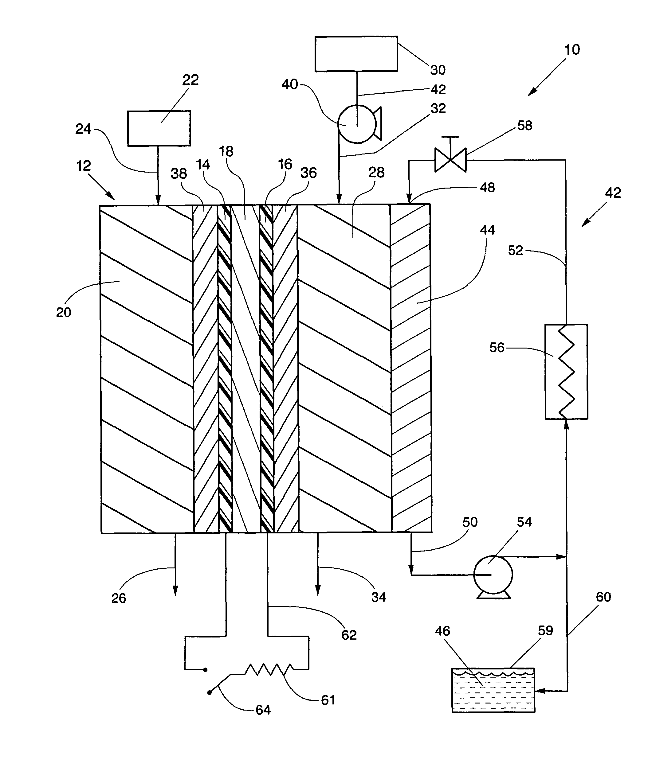
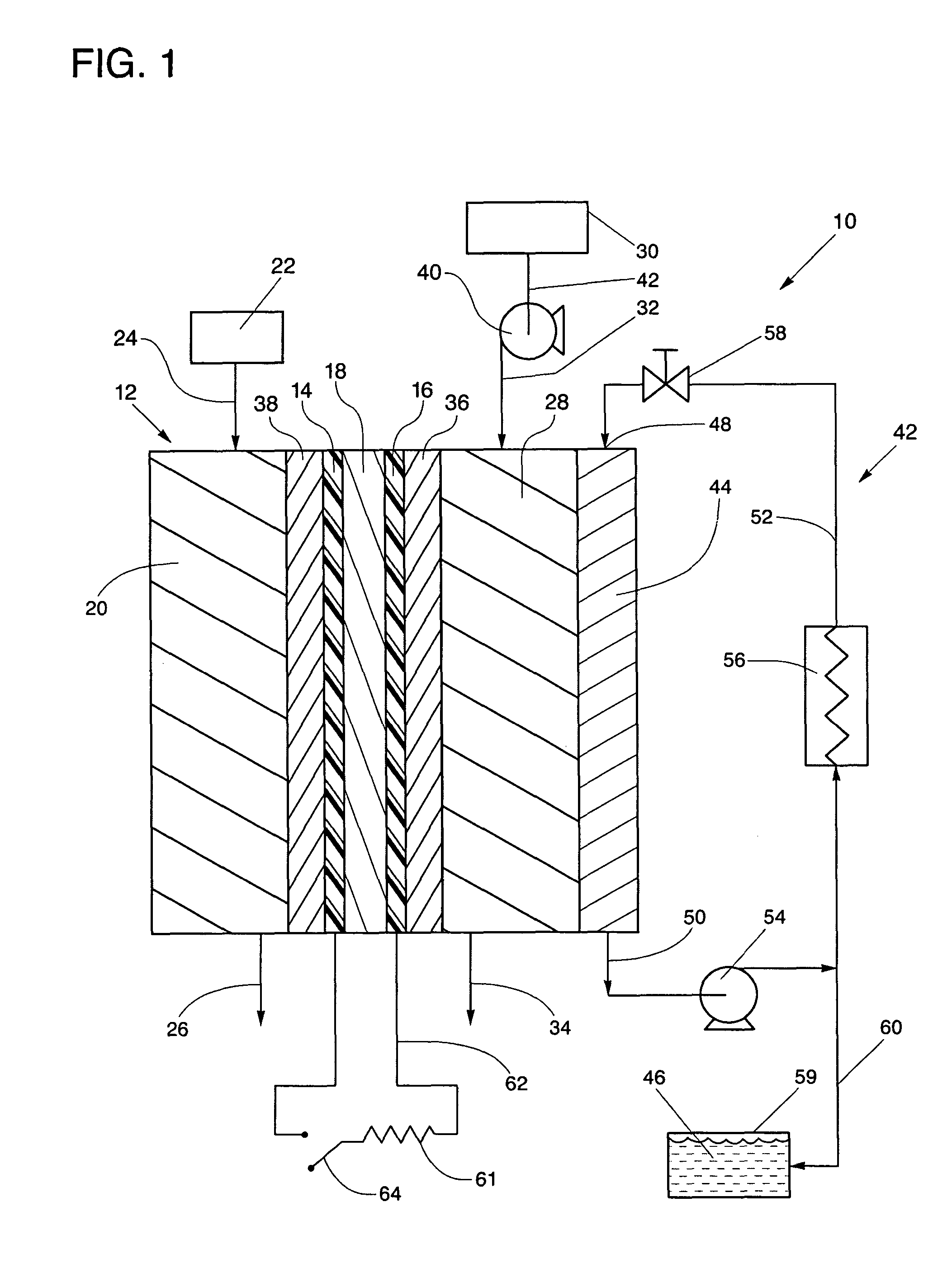
[0021]Referring to the drawings in detail, a fuel cell power plant having improved operating efficiencies is shown in FIG. 1, and is generally designated by the reference numeral 10. The power plant includes at least one fuel cell 12 having an anode catalyst 14 and a cathode catalyst 16 secured to opposed sides of an electrolyte 18, such as a proton exchange membrane electrolyte 18. An anode flow field 20 is defined in fluid communication with the anode catalyst 14 and with a source 22 of the hydrogen rich reactant for directing flow of the hydrogen rich reactant from an anode flow field inlet 24, adjacent the anode catalyst 14 and out of the anode flow field 20 through an anode flow field exit 26. A cathode flow field 28 is also defined in fluid communication with the cathode catalyst 16 and with an oxidant source 30 for directing flow of the oxidant from a cathode flow field inlet 32, adjacent the cathode catalyst 16 and out of the cathode flow field 28 through a cathode flow fiel...


PUM


Abstract

A fuel cell power plant (10) includes an oxidant stream controlled to enter a fuel cell (12) of the plant at a pressure of between about 0.058 pounds per square inch gas (‘psig’) and about 4.4 psig and the oxidant stream passes through the fuel cell (12) at an oxidant stoichiometry of between about 120% and about 180%, and preferably between about 150% and 170%. A macro-pore cathode gas diffusion layer (36) is secured between a cathode catalyst (16) and a cathode flow field (28). A porous coolant plate (44) is secured in fluid communication with and adjacent the cathode flow field (28). The gas diffusion layer (36) and coolant plate (44) facilitate removal of product water to eliminate flooding and to permit operation at low oxidant stoichiometry and high water balance temperature, thereby minimizing need for water capture and heat rejection apparatus.

Description

TECHNICAL FIELD[0001]The present disclosure relates to fuel cell power plants that are suited for usage in transportation vehicles, portable power plants, or as stationary power plants, and the disclosure especially relates to a fuel cell power plant that operates efficiently at low oxidant stoichiometries and low pressure drop, and that thereby minimizes need for water recovery devices, heat rejection apparatus and complex pressure control valves.BACKGROUND ART[0002]Fuel cells are well known and are commonly used to produce electrical current from hydrogen containing reducing fluid fuel and oxygen containing oxidant reactant streams to power electrical apparatus such as transportation vehicles. As is well known in the art, a plurality of fuel cells are typically stacked together to form a fuel cell stack assembly which is combined with controllers, thermal management systems, and other components to form a fuel cell power plant.[0003]In fuel cells of the prior art considerable effo...

Claims


Application Information

Patent Timeline
IPC IPC(8): H01M8/04
CPCH01M8/023H01M8/04029H01M8/04074H01M8/04164H01M8/04179H01M8/04343Y02E60/50H01M8/04358H01M8/04716H01M8/04723H01M8/04753H01M8/04768H01M2008/1095H01M8/0435
Inventor PERRY, MICHAEL L.DARLING, ROBERT M.
Owner AUDI AG
Learn More