
Capacitive touch screen with reduced electrode trace resistance

a capacitive touch screen and electrode trace technology, applied in the field of capacitive touch screens, can solve the problem of small width, achieve the effect of reducing the overall electrode trace resistance, increasing electrical performance, and improving electrical performan

Inactive Publication Date: 2010-12-30
OCULAR LCD
View PDF5 Cites 134 Cited by
  • Summary
  • Abstract
  • Description
  • Claims
  • Application Information

AI Technical Summary

Benefits of technology

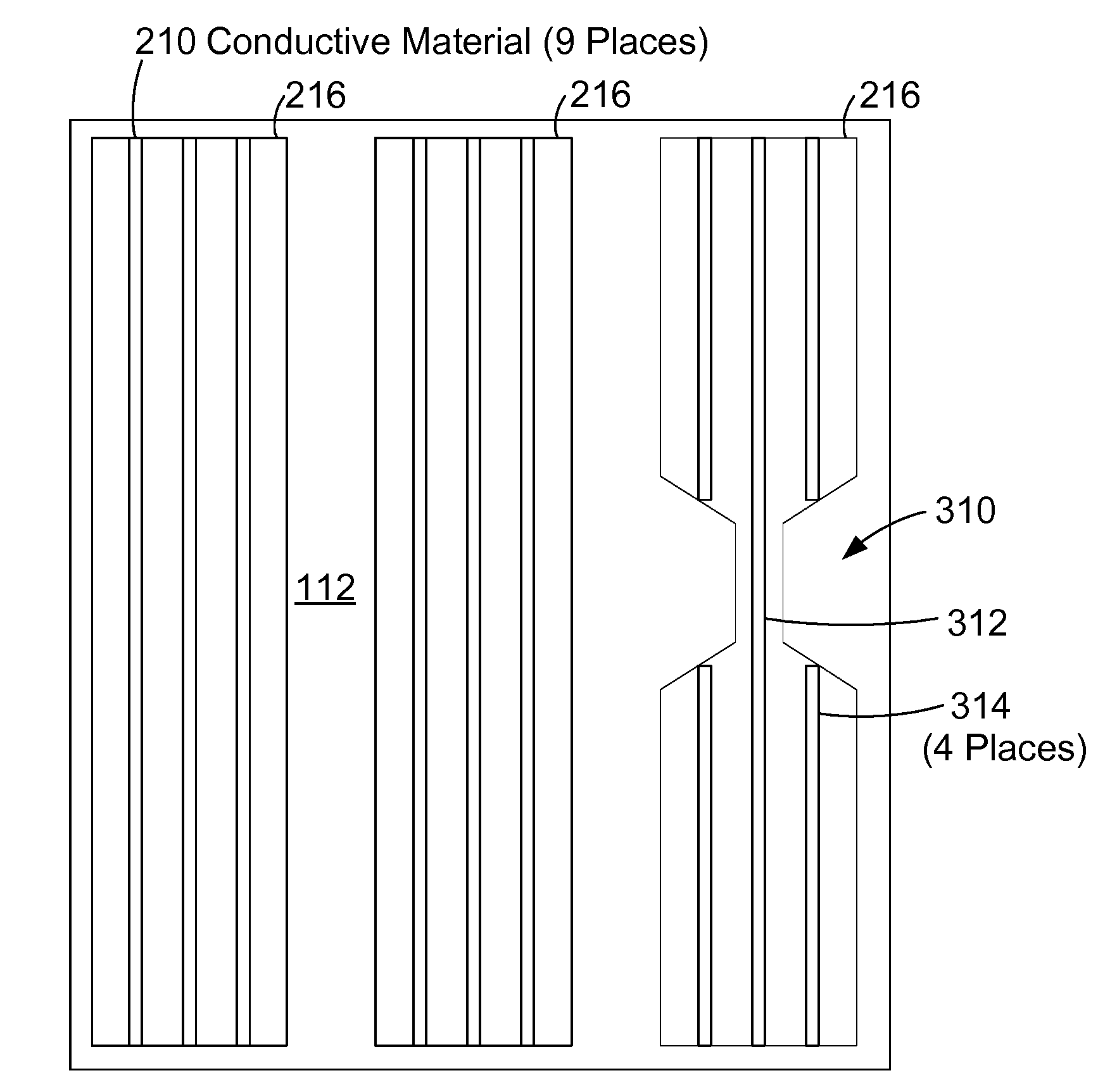
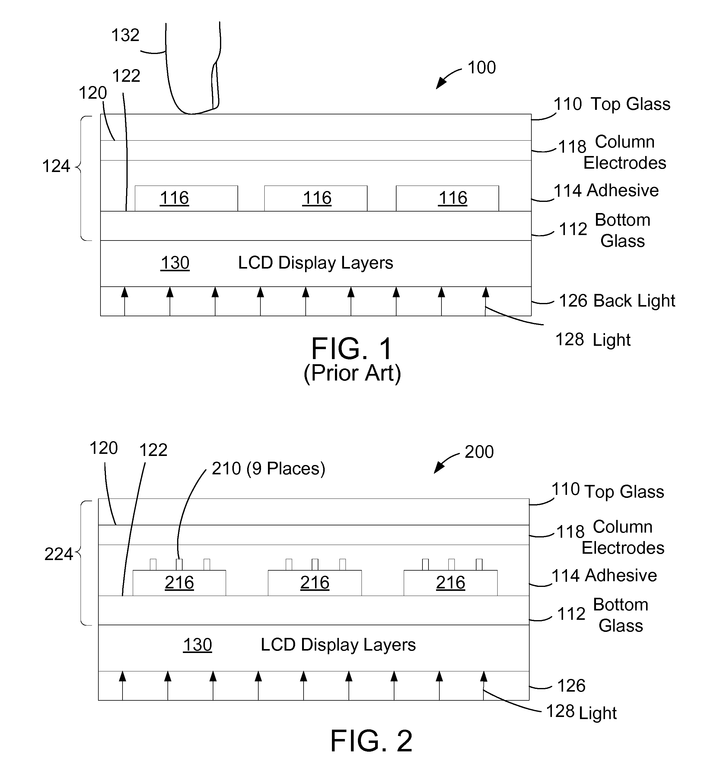
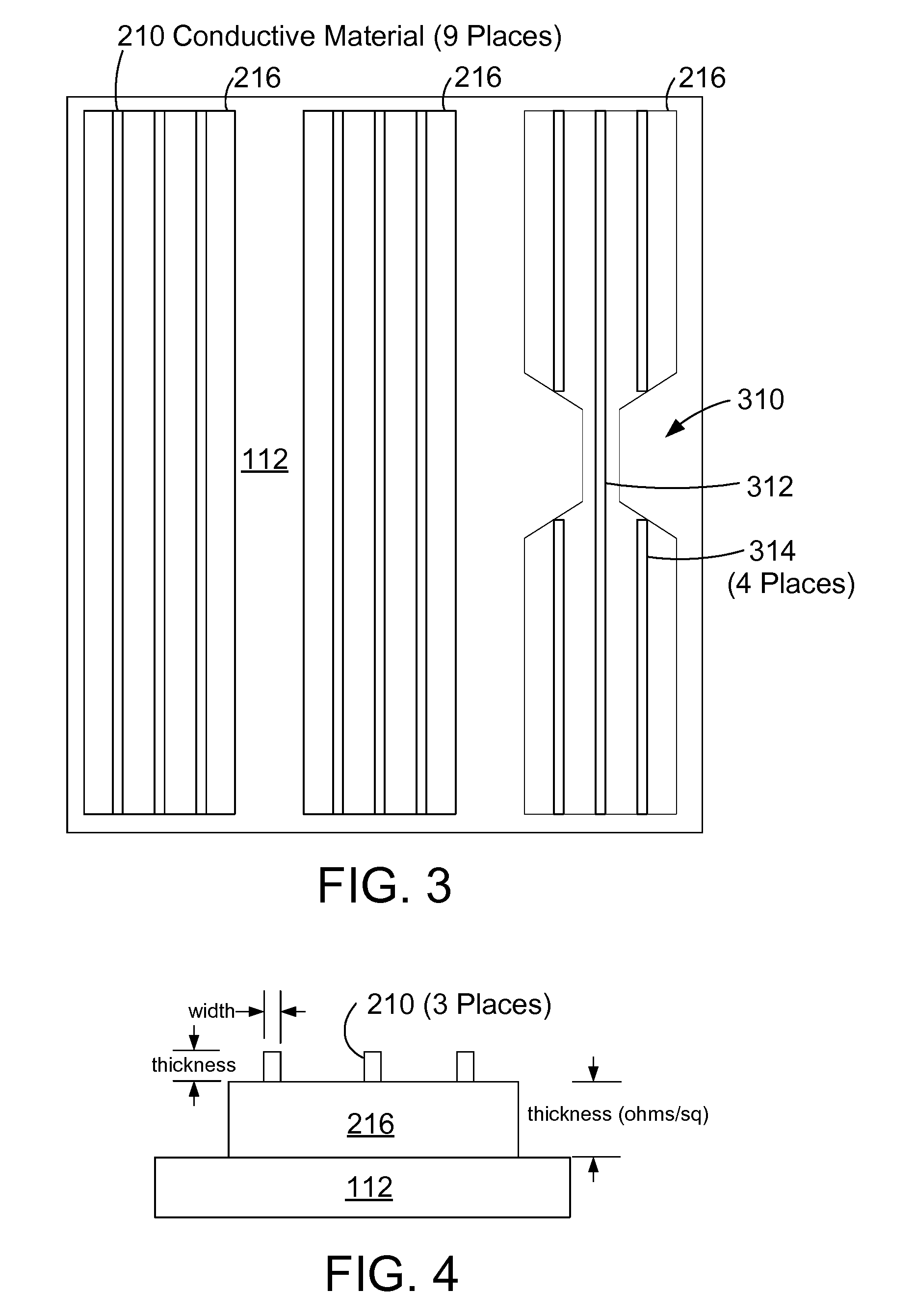
[0006]The application and claims herein are directed to an improved touch screen with enhanced electrical performance and optical quality. The electrodes on the touch screen employ additional fine traces of conductive material to reduce the overall electrode trace resistance to increase electrical performance without sacrificing optical quality. The additional fine traces of conductive material may be placed on the top of the ITO traces or in channels inside the boundaries of the ITO traces. The additional traces run the length of the ITO traces to reduce the resistance in the longer dimension. Further, the additional traces are very small in width such that in the aggregate they cover only a small portion of the ITO electrode trace in lateral dimension to reduce the visibility of the additional traces. The conductive material may also be formed as a plurality of geometric shapes substantially forming a line in the longer dimension of the transparent conductive traces to reduce the visibility of the conductive material.

Problems solved by technology

Further, the additional traces are very small in width such that in the aggregate they cover only a small portion of the ITO electrode trace in lateral dimension to reduce the visibility of the additional traces.

Method used


Image

  • Capacitive touch screen with reduced electrode trace resistance
  • Capacitive touch screen with reduced electrode trace resistance
  • Capacitive touch screen with reduced electrode trace resistance

Examples


Embodiment Construction

[0018]The description and claims herein are directed to an improved touch screen. The electrodes and other ITO traces on the touch screen employ additional fine traces of conductive material to reduce the overall electrode trace resistance to increase electrical performance without sacrificing optical quality. The additional fine traces of conductive material may be placed on the top of the ITO traces or in channels inside the boundaries of the ITO traces. The additional traces preferably run the length of the ITO traces to reduce the resistance in the longer dimension. Further, the additional traces are very small in width such that in the aggregate they cover only a small portion of the ITO electrode trace in lateral dimension to reduce the visibility of the additional traces.

[0019]The optical quality of a touch screen panel can be described in terms of transparency, where 100% transparent means 100% of the light transfers through the panel. A typical single layer of glass used in...


PUM


Abstract

An improved touch screen has enhanced optical performance and aesthetic quality. The electrodes on the touch screen employ additional fine traces of conductive material to reduce the overall electrode trace resistance to increase electrical performance without sacrificing optical quality. The additional fine traces of conductive material may be placed on the top of the ITO traces or in channels inside the boundaries of the ITO traces. The additional traces preferably run the length of the ITO traces to reduce the resistance in the longer dimension. Further, the additional traces are very small in width such that in the aggregate they cover only a small portion of the ITO electrode trace in lateral dimension to reduce the visibility of the additional traces. The conductive material may also be formed as a plurality of geometric shapes substantially forming a line in the longer dimension of the transparent conductive traces to reduce the visibility of the conductive material.

Description

BACKGROUND[0001]1. Technical Field[0002]The disclosure and claims herein generally relate to touch screens, and more specifically relate to a touch screen with improved optical performance by adding additional conductive materials to reduce the resistance of the electrode traces.[0003]2. Background Art[0004]Touch screens have become an increasingly important input device. Touch screens use a variety of different touch detection mechanisms. One important type of touch screen is the capacitive touch screen. Capacitive touch screens are manufactured via a multi-step process. In a typical touch screen manufacturing process, a transparent conductive coating, such as indium tin oxide (ITO) is formed into conductive traces or electrodes on two surfaces of glass. The conductive traces on the two surfaces of glass typically form a grid that can sense the change in capacitance when a user's finger or a pointer touches the screen near an intersection of the grid. Thus the capacitive touch scre...

Claims


Application Information

Patent Timeline
IPC IPC(8): G06F3/044G06F3/041
CPCG06F2203/04111G06F3/044G06F3/0445
Inventor MOZDZYN, LARRY STEPHEN
Owner OCULAR LCD
Learn More