
Catheter Tip Positioning Method

a catheter tip and positioning technology, applied in the field of catheter tip positioning, can solve the problems of difficult interaction between patient and patient, the use of communication channels, telephone lines, etc., and the acceptance of remote monitoring of heart conditions is not as widespread

Active Publication Date: 2010-12-16
BARD ACCESS SYST
View PDF100 Cites 125 Cited by
  • Summary
  • Abstract
  • Description
  • Claims
  • Application Information

AI Technical Summary

Benefits of technology

[0134]The many features and advantages of the invention are apparent from the detailed specification, and, thus, it is intended by the appended claims to cover all such features and advantages of the invention which fall within the true spirit and scope of the invention. Further, since numerous modifications and variations will readily occur to those skilled in the art, it is not desired to limit the invention to the exact construction and operation illustrated and described, and, accordingly, all suitable modifications and equivalents may be resorted to that fall within the scope of the invention.

Problems solved by technology

The chest X-ray, which is the current golden standard does not always allow for such discrimination requiring an accuracy of typically better than 2 cm.
Still remote monitoring of heart conditions is not as widely accepted as it would be need and possible.
One of the reasons is related to the relatively complicated way of acquiring signals related to the heart activity, in particular ECG signals.
Another important limiting factor of the current remote monitoring technologies is the use of communications channels, like the telephone line, which are difficult to interface with at both the patient and the physician ends.

Method used


Image

  • Catheter Tip Positioning Method
  • Catheter Tip Positioning Method
  • Catheter Tip Positioning Method

Examples


Embodiment Construction

[0036]The invention will now be described with reference to the drawing figures, in which like reference numerals refer to like parts throughout.

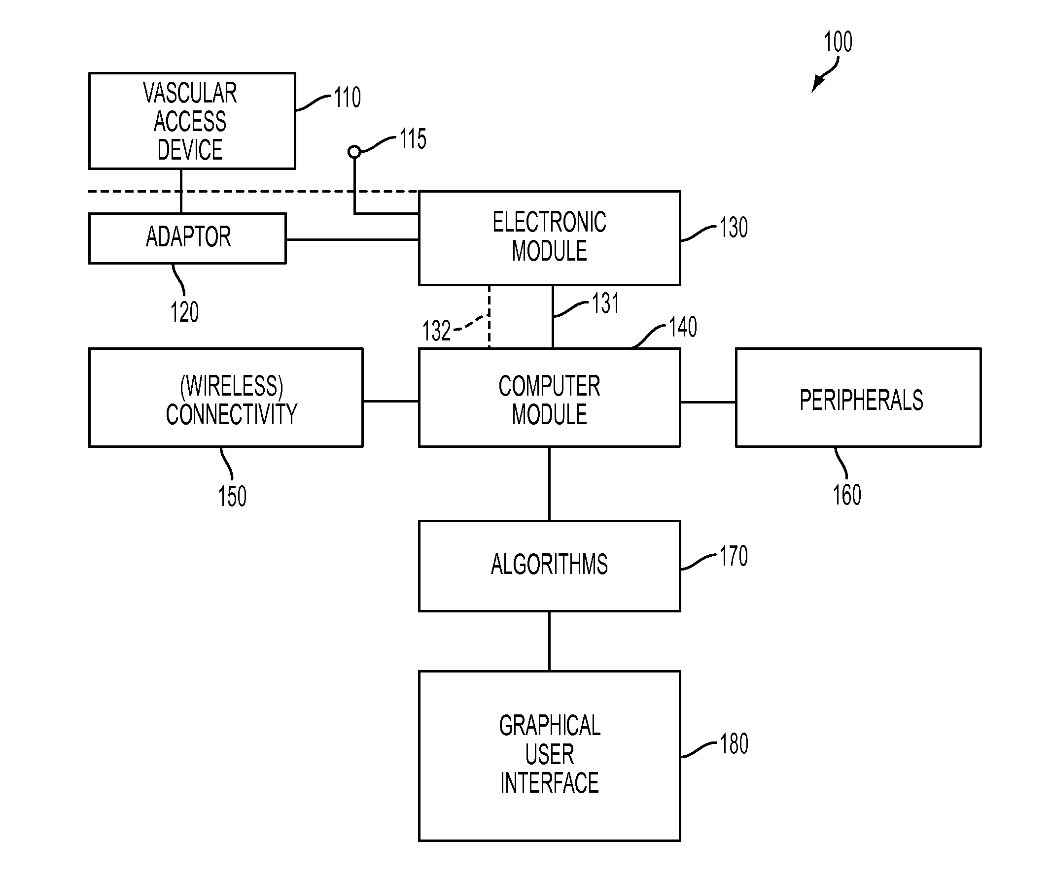
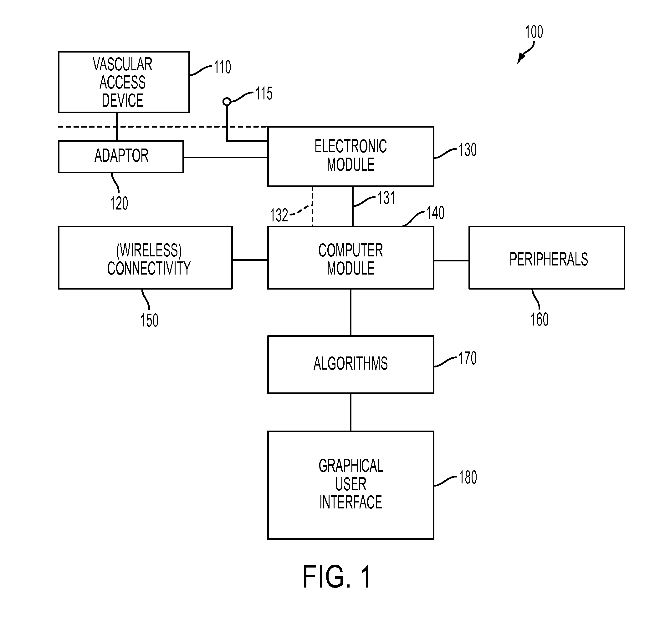
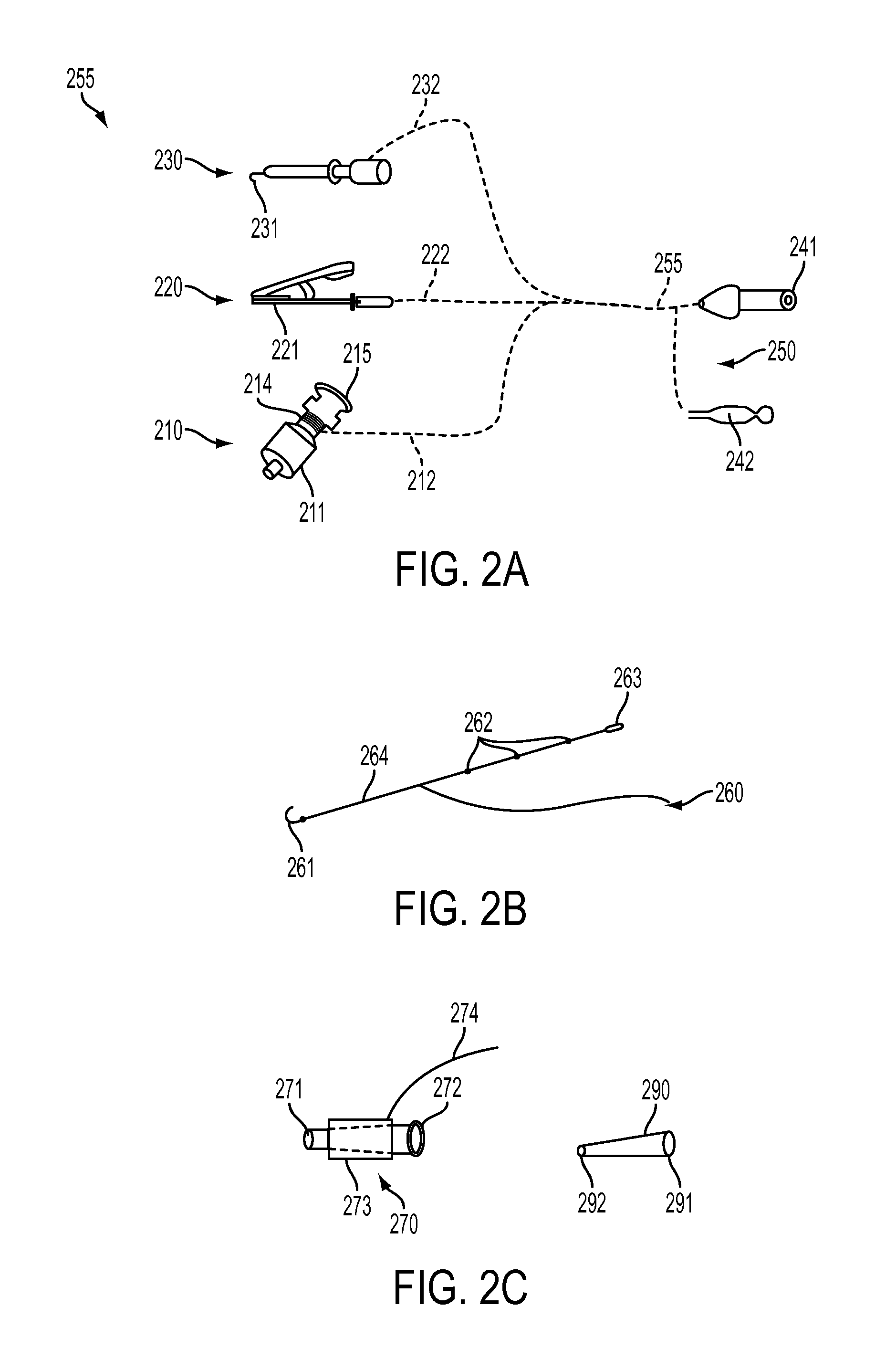
[0037]Embodiments of the present invention advantageously provide an inventive apparatus(es), computer-based data processing algorithms and methods for obtaining and using endovascular ECGs in a number of clinical applications and settings. For example, once device can be used to guide endovascular devices in and around the heart, e.g., guiding central venous access devices in the superior vena cava, right atrium, and right ventricle. Such central venous access devices may include central venous catheters (CVC), peripherally inserted central catheters (PICC), implantable ports, hemodialysis catheters, tunneled catheters and others. Other devices which may benefit from guidance with the inventive apparatus are temporary pacemaker leads placed through the central venous system. Catheters and guidewires used in left heart procedures may also b...


PUM


Abstract

A computer-based method for positioning an endovascular device in or near the heart using electrocardiogram (ECG) signals is provided. The computer-based method includes receiving an endovascular ECG signal, associated with an endovascular device, including a plurality of waveforms, each waveform having at least a P-wave component, processing the endovascular ECG signal, over a plurality of predetermined time periods, to calculate a P-wave amplitude and a spectral power for each predetermined time period, determining a maximum P-wave amplitude from the plurality of P-wave amplitudes, and an associated maximum spectral power from the plurality of spectral powers, associating the maximum P-wave amplitude and the maximum spectral power with a predetermined location in or near the heart, calculating a location of the endovascular device, for each predetermined time period, based on a ratio of the P-wave amplitude to the maximum P-wave amplitude and a ratio of the spectral power to the maximum spectral power, and displaying the location of the endovascular device to a user.

Description

CROSS-REFERENCE TO RELATED APPLICATIONS[0001]This application claims priority to U.S. Provisional Patent Application Ser. No. 61 / 213,474, filed on Jun. 12, 2009, the disclosure of which is incorporated herein by reference in its entirety.FIELD OF THE INVENTION[0002]The present invention relates to a endovascular device positioning. Specifically, the present invention relates to a method for positioning the tip of an endovascular device, such as a central venous catheter, in and around the heart using electrocardiogram (ECG) signals.BACKGROUND OF THE INVENTION[0003]The electrical conduction system of the heart creates specific electrical signals, electrical energy distributions and behaviors thereof which are indicative of specific locations in the thoracic cavity and / or of specific heart functions or conditions. When measured endovascularly, i.e., from within blood vessels or from within the heart, certain parameters of the electrical activity of the heart can be used to identify sp...

Claims


Application Information

Patent Timeline
Patent Type & Authority Applications(United States)
IPC IPC(8): A61B5/0456A61B5/352A61B5/361A61B5/276A61B5/296A61B5/364
CPCA61B5/04017A61B5/042A61B19/5244A61B5/06A61B5/726A61B5/0452A61B34/20A61B5/065A61B5/316A61B5/283A61B5/349A61M25/0105A61B5/353A61B5/743A61B5/6876A61B5/6852A61B5/7246A61M25/0014A61M2039/1077A61M2039/1083A61M2039/1088A61B5/347
Inventor GRUNWALD, SORIN
Owner BARD ACCESS SYST
Learn More