
Web Substrate Deposition System

a deposition system and substrate technology, applied in the direction of electrolysis components, vacuum evaporation coatings, coatings, etc., can solve the problems of web material wrinkling and crease on the drum, web material receiving a very high heat load during deposition, and increasing with the deposition ra

Inactive Publication Date: 2010-11-18
VEECO INSTR
View PDF11 Cites 24 Cited by
  • Summary
  • Abstract
  • Description
  • Claims
  • Application Information

AI Technical Summary

Benefits of technology

[0002]The present invention relates to web substrate deposition systems. Web substrate deposition systems have been used for processing webs of numerous types of flexible substrate materials for many years. In these deposition systems, the plastic web is tightly spooled over a rotating cooling drum positioned above an evaporation source. The plastic web material receives a very high heat load during deposition from condensing metal and from radiant heat which typically increases with the deposition rate. Thus, when operating at high transport rates to achieve high coating speeds, this heat load may cause the web material to wrinkle and crease on the drum. This wrinkling and creasing on the drum can permanently damage the web substrate. The thermal conductance between the web substrate and the cooling drum plays an important role in controlling the temperature rise of the web substrate as it is coated. The temperature rise is important because it sets an upper limit on the coating speed for a given web substrate and deposition process.

Problems solved by technology

The plastic web material receives a very high heat load during deposition from condensing metal and from radiant heat which typically increases with the deposition rate.
Thus, when operating at high transport rates to achieve high coating speeds, this heat load may cause the web material to wrinkle and crease on the drum.
This wrinkling and creasing on the drum can permanently damage the web substrate.

Method used


Image

  • Web Substrate Deposition System
  • Web Substrate Deposition System
  • Web Substrate Deposition System

Examples


Embodiment Construction

[0008]Reference in the specification to “one embodiment” or “an embodiment” means that a particular feature, structure, or characteristic described in connection with the embodiment is included in at least one embodiment of the invention. The appearances of the phrase “in one embodiment” in various places in the specification are not necessarily all referring to the same embodiment.

[0009]It should be understood that the individual steps of the methods of the present teachings may be performed in any order and / or simultaneously as long as the invention remains operable. Furthermore, it should be understood that the apparatus and methods of the present teachings can include any number or all of the described embodiments as long as the invention remains operable.

[0010]The present teachings will now be described in more detail with reference to exemplary embodiments thereof as shown in the accompanying drawings. While the present teachings are described in conjunction with various embod...


PUM

PropertyMeasurementUnit
pressureaaaaaaaaaa
diameteraaaaaaaaaa
heataaaaaaaaaa

Abstract

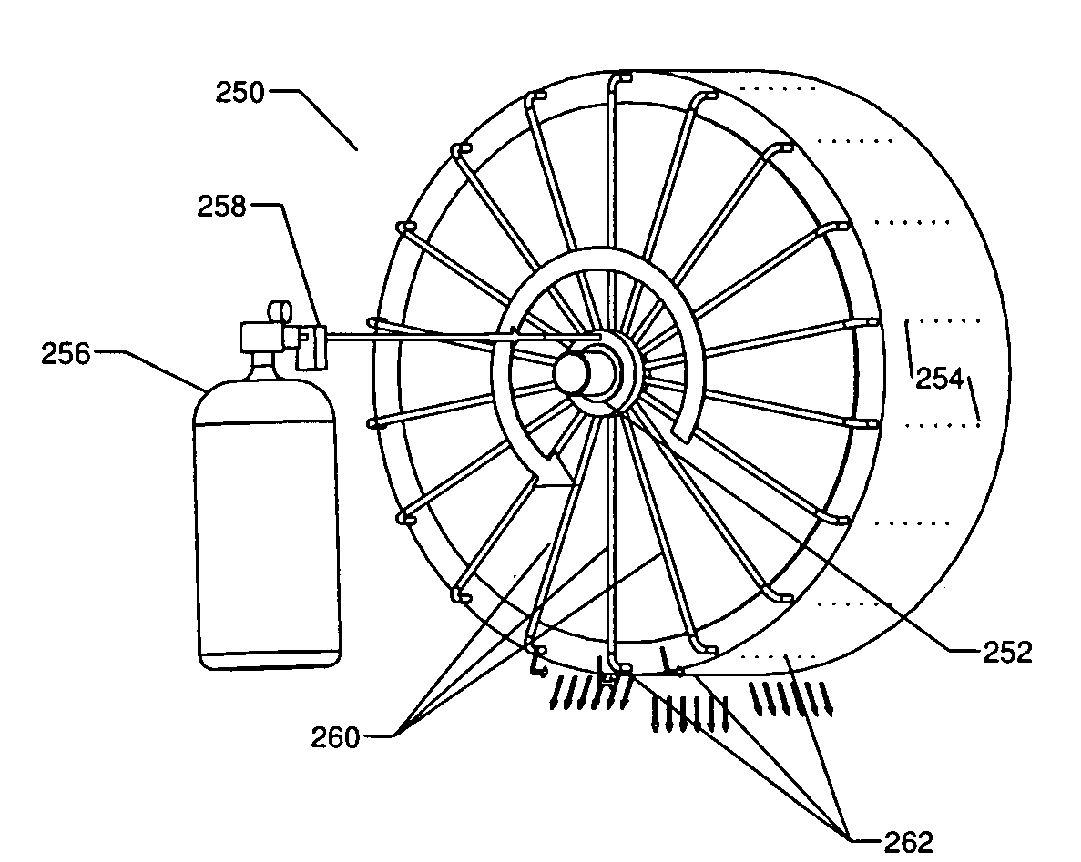
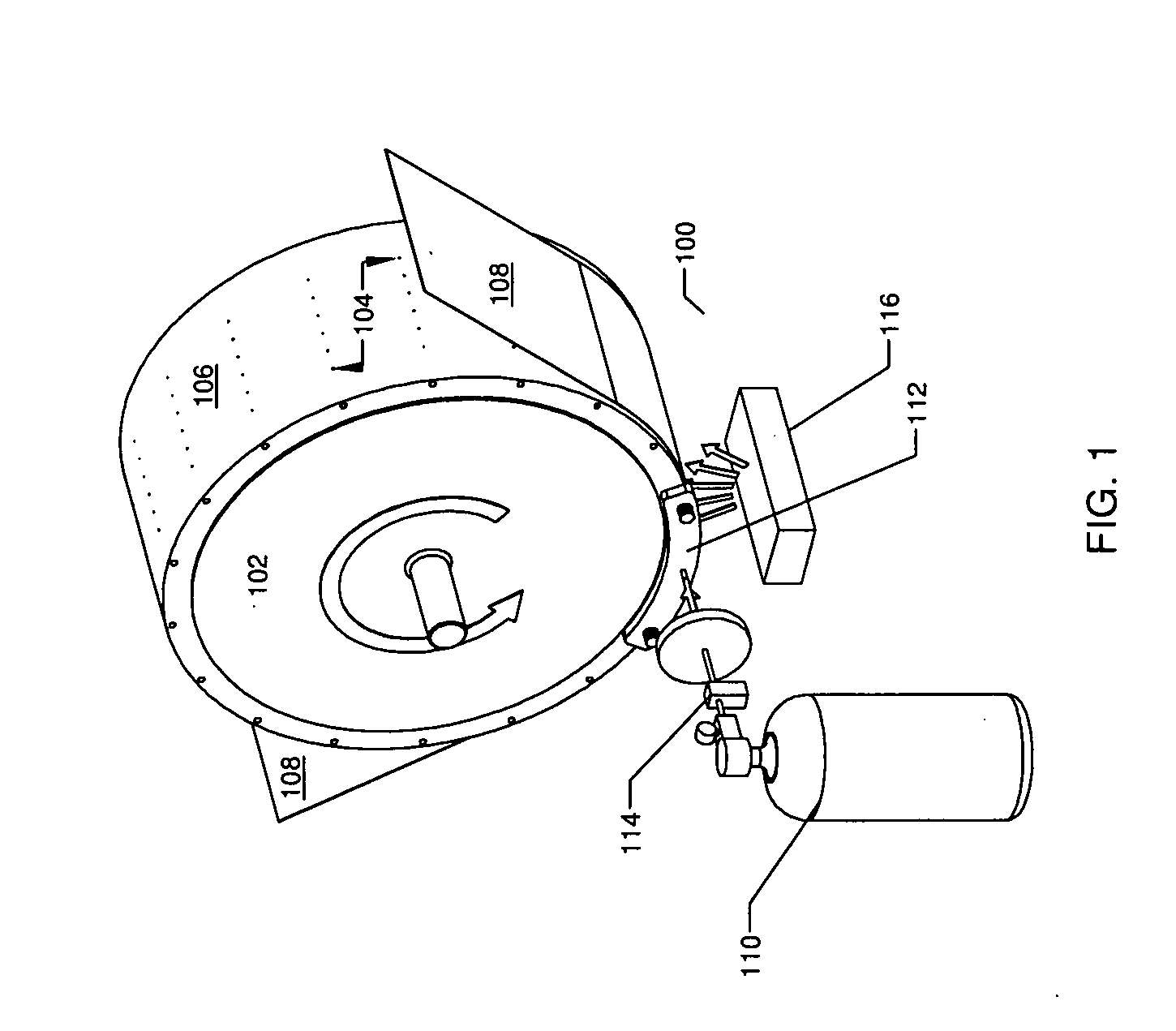
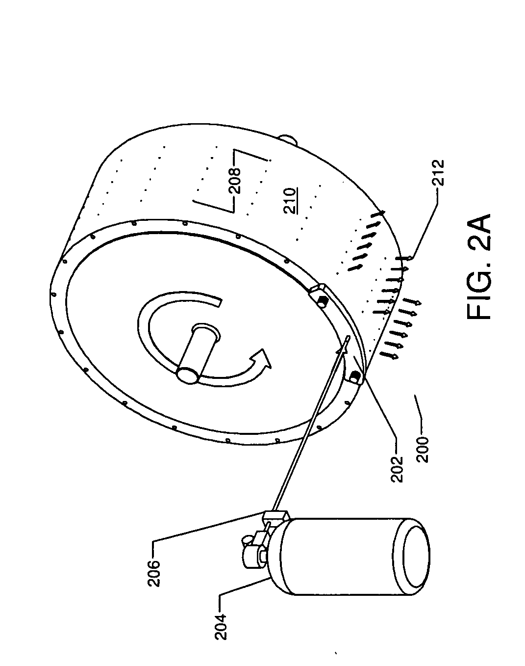
A deposition system includes a drum for supporting a web substrate during deposition that defines a plurality of apertures in an outer surface for passing cooling gas. A gas manifold includes an input that is coupled to an output of a gas source and at least one output that is coupled to the plurality of apertures in the outer surface of the drum. The gas manifold provides gas to the plurality of apertures that flows between the outer surface of the drum and the web substrate, thereby increasing heat transfer from the web substrate to the drum. At least one deposition source is positioned so that material deposits on the web substrate.

Description

[0001]The section headings used herein are for organizational purposes only and should not to be construed as limiting the subject matter described in the present application in any way.INTRODUCTION[0002]The present invention relates to web substrate deposition systems. Web substrate deposition systems have been used for processing webs of numerous types of flexible substrate materials for many years. In these deposition systems, the plastic web is tightly spooled over a rotating cooling drum positioned above an evaporation source. The plastic web material receives a very high heat load during deposition from condensing metal and from radiant heat which typically increases with the deposition rate. Thus, when operating at high transport rates to achieve high coating speeds, this heat load may cause the web material to wrinkle and crease on the drum. This wrinkling and creasing on the drum can permanently damage the web substrate. The thermal conductance between the web substrate and...

Claims


Application Information

Patent Timeline
Patent Type & Authority Applications(United States)
IPC IPC(8): B05D3/00C23C16/56B05C9/12C23C14/35
CPCC23C14/562C23C14/541
Inventor SFERLAZZO, PIEROKLEIN, MARTIN
Owner VEECO INSTR
Learn More