
Machining apparatus and machining method

a technology of machining apparatus and machining method, which is applied in the direction of numerical control, electrical programme control, instruments, etc., can solve the problems of limited position accuracy, limited position accuracy, and limited machining device and accuracy restrictions, so as to improve shape accuracy and position accuracy of machined shapes, and achieve high optical accuracy. the effect of high accuracy

Inactive Publication Date: 2010-11-04
PANASONIC CORP
View PDF9 Cites 5 Cited by
  • Summary
  • Abstract
  • Description
  • Claims
  • Application Information

AI Technical Summary

Benefits of technology

[0015]The present invention has been devised in view of the conventional problems described above, an object thereof being to provide a machining apparatus and a machining method whereby restrictions on the arrangement of machined shapes can be eased, and the shape accuracy and positional accuracy of the machined shapes can be improved.
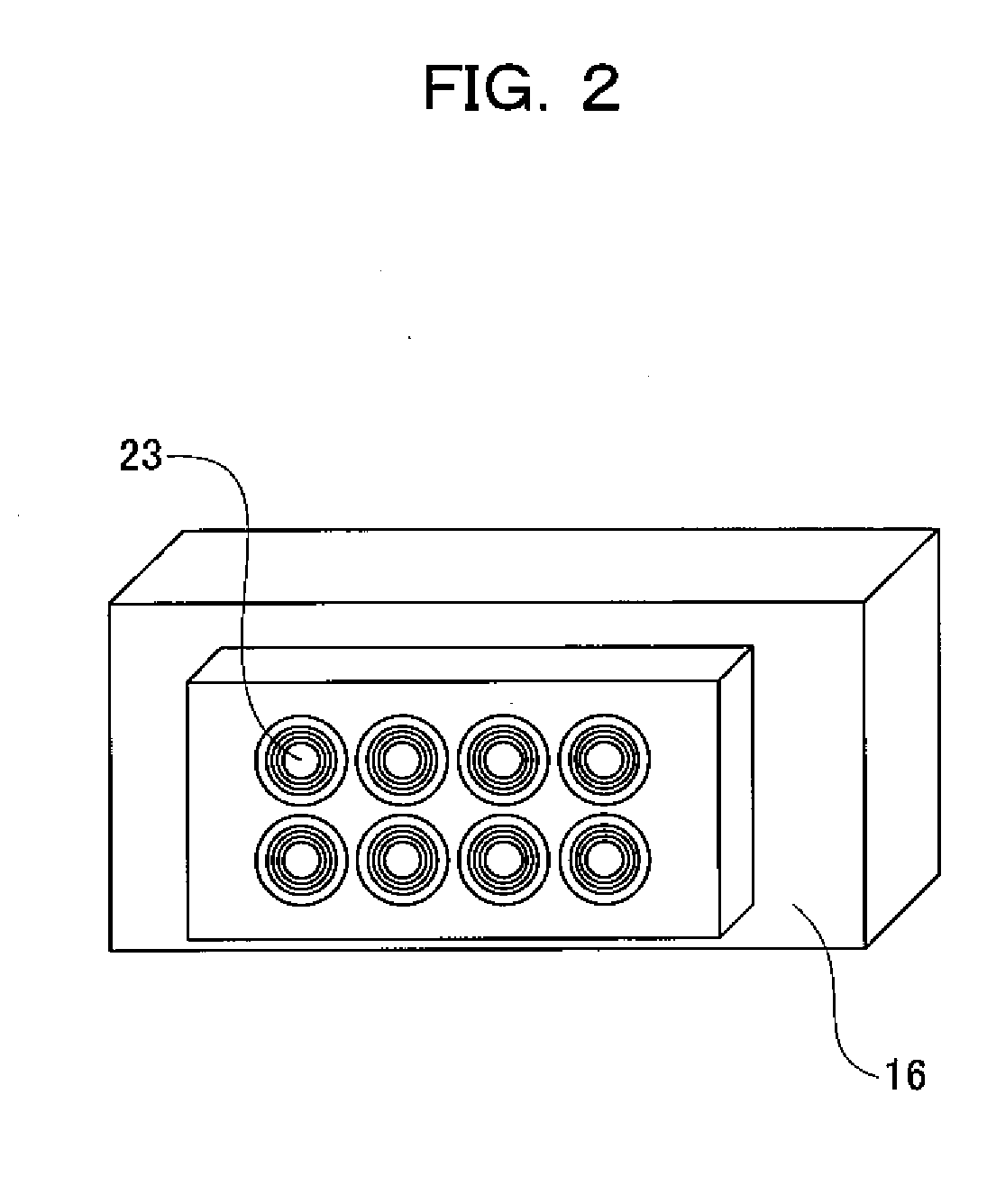
[0030]According to a desirable mode of the present invention, positional restrictions on the machined shapes are eased and the shape accuracy and positional accuracy of the machined shapes are improved. Therefore, according to the desirable mode of the present invention, it is possible to achieve high accuracy in an optical element in which concave surfaces or convex surfaces are arranged in an array configuration, or in a mold or master mold for forming such an optical element.

Problems solved by technology

However, the conventional machining apparatus described above has problems that: (1) the arrangement of the rotational curved surface is limited; (2) variations occur in the shape accuracy of the rotational curved surface; and (3) variations also occur in the positional accuracy of the rotational curved surface.
(1) The arrangement of the rotational curved surface is limited by the restrictions of the machining device and accuracy.
Firstly, the limitations on the arrangement of the rotational curved surface by the restrictions of the machining device will be described.
Thus, the feed velocity of the linear drive axis increases with the distance of the offset position O′ from the rotation center O. However, in current ultra-high-precision machining apparatuses, a feed velocity of over 1000 [mm / min] is not realistic from the viewpoint of accuracy improvement.
The rotation speed of the rotating drive shaft may conceivably be reduced and the linear drive axis may be operated within the limits of the feed velocity of the linear drive axis as a measure, but such a method requires a huge amount of machining time.
If the machining time becomes too long, then changes in temperature and humidity and vibrations caused by comings and goings of staff to and from a room where the machining apparatus is located have an effect, making it difficult to improve the accuracy of a machined shape.
Furthermore, in the case of a cutting operation using a cutting tool, if the rotation speed is too slow, then there is a risk of wear of the tool and the deterioration of surface texture (surface property and state) of the workpiece involved.
Furthermore, as the distance from the rotation center O to the offset position O′ increases, then an error in the resolution pitch of the rotational drive axis 2 also increases.
Moreover, as described above, the larger the distance of the offset position O′ from the rotation center O, the larger the error in the resolution pitch of the rotational drive shaft 2.
Consequently, the error in this resolution pitch also causes variations in the positional accuracy of the rotational curved surface.

Method used


Image

  • Machining apparatus and machining method
  • Machining apparatus and machining method
  • Machining apparatus and machining method

Examples


Embodiment Construction

[0038]Below, an embodiment of the present invention is described referring to the drawings. In the respective drawings, the same constituent elements are labelled with the same reference numerals and duplicated description thereof is omitted.

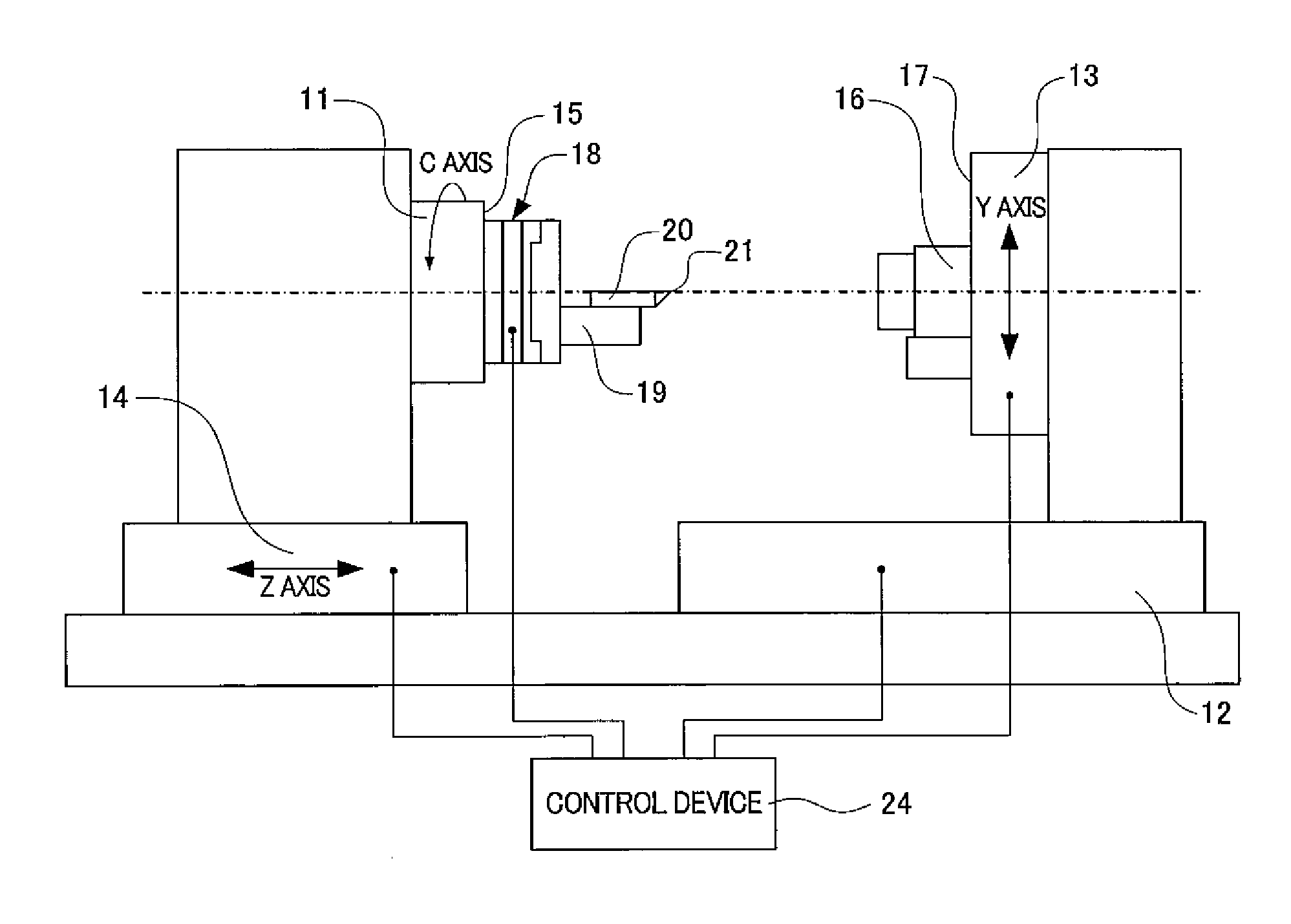
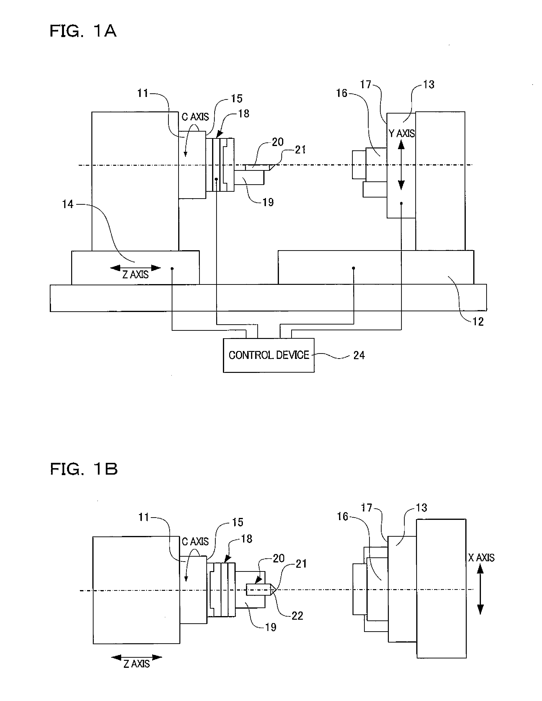
[0039]As shown in FIG. 1A and FIG. 1B, a machining apparatus includes a rotational drive shaft 11, an X axis table 12, a Y axis table 13 and a Z axis table 14. The X axis table 12, Y axis table 13 and Z axis table 14 constitute three linear drive axes which advance linearly in three axial directions orthogonal to each other.

[0040]A tool mounting surface 15 is provided on the rotational drive shaft 11 so as to be orthogonal to the rotation axis (C axis) of the shaft 11. A machining tool is mounted on the tool mounting surface 15. Meanwhile, a workpiece mounting surface 17 is provided on the Y-axis table 13. A workpiece 16 is mounted on the workpiece mounting surface 17.

[0041]The rotational drive shaft 11 is provided on the Z-axis table 14 which i...


PUM


Abstract

A machining apparatus capable of easing positioning restrictions on machined shapes and improving the shape accuracy and positional accuracy of the machined shapes. A machining tool forms a machined shape in a workpiece mounted on a workpiece mounting surface, by means of a rotational shaft causing the machining tool to rotate, and three linear axes moving the machining tool so as to follow the machined shape of a machining object while moving the center of the intended formation region of the machined shape of the machining object in a circular arc shape in accordance with the rotation of the machining tool.

Description

[0001]The disclosure of Japanese Patent Application No. 2009-110227 filed Apr. 30, 2009 including specification, drawings and claims is incorporated herein by reference in its entirety.BACKGROUND OF THE INVENTION[0002]1. Field of the Invention[0003]The present invention relates to a machining apparatus and a machining method for forming a machined shape such as an axially symmetrical shape, an axially asymmetrical shape, or a free form surface shape in a workpiece for machining.[0004]2. Description of the Related Art[0005]In recent years, with progress in the miniaturization, improved performance, and increased capacity of optical equipment, advances have been made in reducing the curvature and diameter of optical elements used in optical equipment, as well as improving accuracy and achieving complex shapes. Against this background, optical elements are present in which spherical or aspherical concave surfaces or convex surfaces are arranged in an array configuration. In an optical ...

Claims


Application Information

Patent Timeline
IPC IPC(8): G05B19/19
CPCB24B13/06
Inventor TAKAMI, FUMINORIKUBO, MASAHIRO
Owner PANASONIC CORP
Learn More