
Memory management method, memory management program, and memory management device

a memory management and memory management technology, applied in the direction of memory adressing/allocation/relocation, micro-instruction address formation, instruments, etc., can solve the problems of deteriorating affecting the processing efficiency of the entire virtual machine system, so as to increase the utilization efficiency of physical memory.

Inactive Publication Date: 2010-10-28
HITACHI LTD
View PDF3 Cites 30 Cited by
  • Summary
  • Abstract
  • Description
  • Claims
  • Application Information

AI Technical Summary

Benefits of technology

[0016]Accordingly, the present invention has for its main object to solve the aforementioned problems by raising the utilization efficiency of the utilized physical memory in a virtual machine system built of a plurality of virtual machines.
[0022]According to the present invention, it is possible to increase the utilization efficiency of the utilized physical memory in a virtual machine system built of a plurality of virtual machines.

Problems solved by technology

As mentioned above, if the respective physical memory allocations of a plurality of virtual machines end up becoming unbalanced, the utilization efficiency of physical memory ends up deteriorating, and the processing efficiency of the entire virtual machine system ends up worsening.
As a result, it is necessary to wait for the occurrence of memory shortage, so, accompanying the program memory shortage, there ends up occurring a decline in the processing efficiency.
Also, as for the technology in Waldspurger, the applications operating on the OS of a virtual machine are ensured, but it is not possible to release unused memory.
As for the technology of JP-A-2005-208785, in case there is not the relationship that, in case the memory use level of one task has increased, the memory use level of another task diminishes, there is the possibility that the memory that is required simultaneously increases, in which case memory shortages are provoked more easily.
Also, a plurality of tasks cannot be accommodated.

Method used


Image

  • Memory management method, memory management program, and memory management device
  • Memory management method, memory management program, and memory management device
  • Memory management method, memory management program, and memory management device

Examples


Embodiment Construction

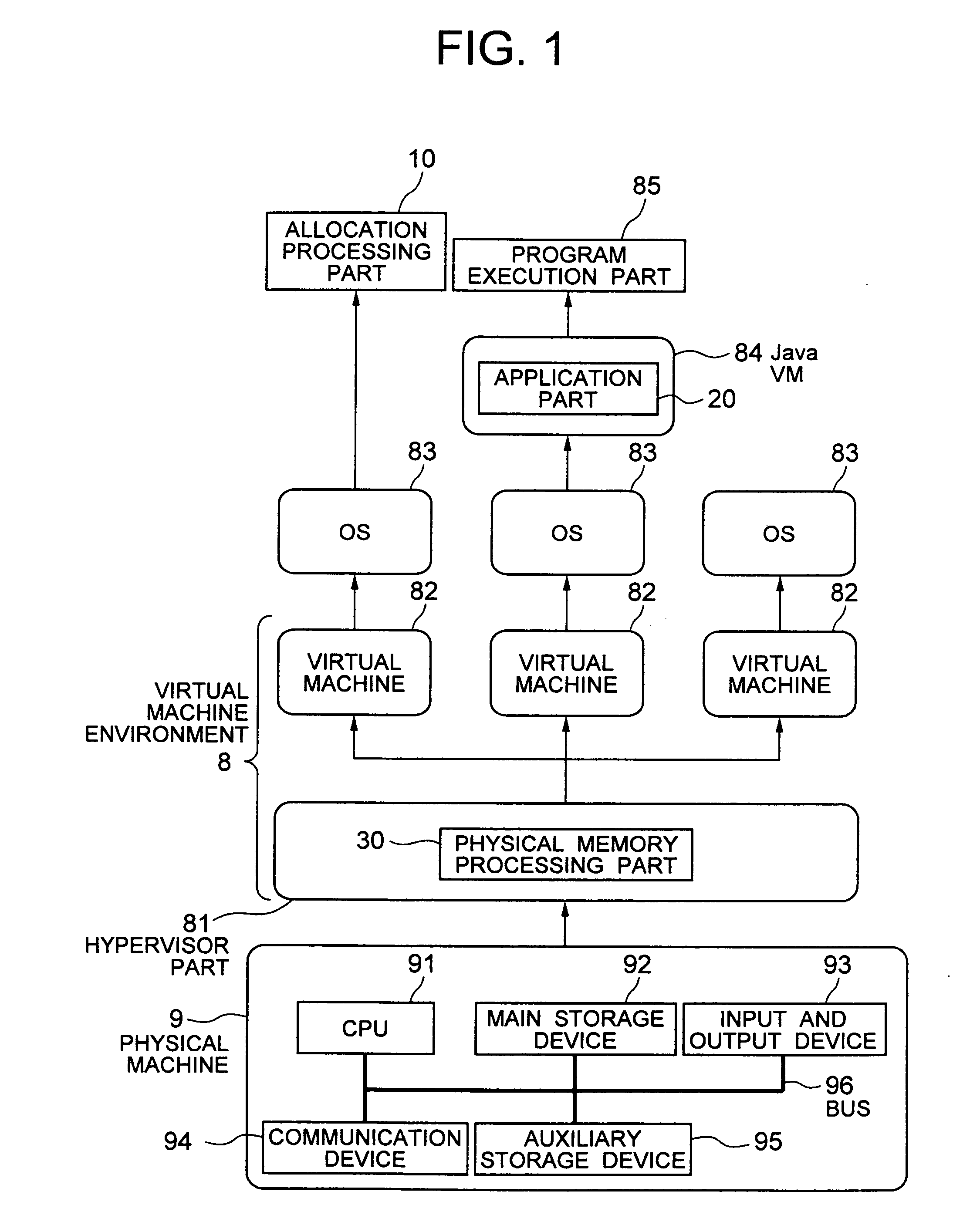
[0032]Hereinafter, an embodiment of the present invention will be described in detail with reference to the drawings.

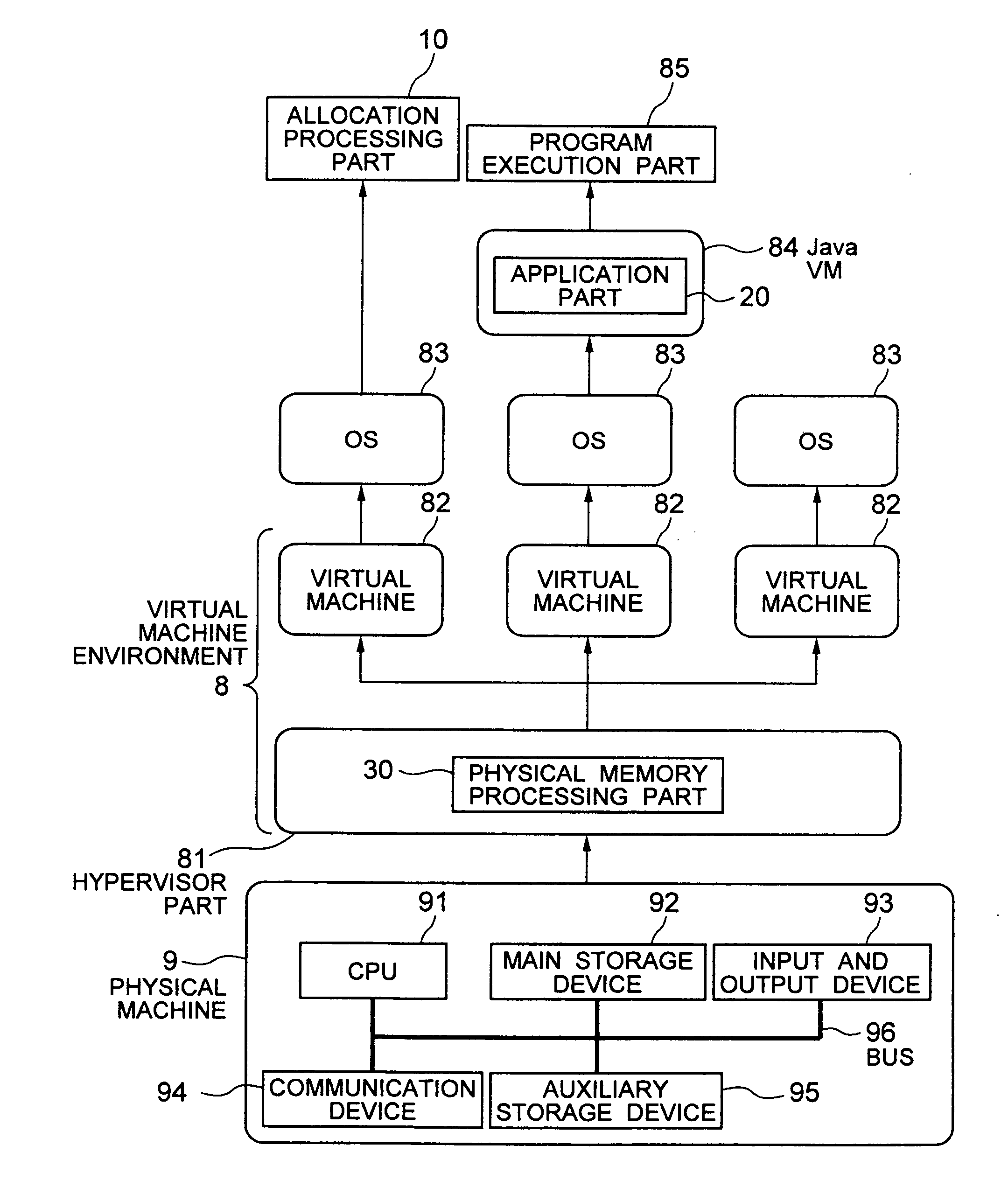
[0033]FIG. 1 is a block diagram showing a physical machine 9 on which a virtual machine environment 8 is built. In FIG. 1, there is shown a layer model of virtual machine environment 8 by indicating arrows pointing from a lower level to a higher level. E.g., an arrow from physical machine 9 to a hypervisor part 81 is included, and this arrow indicates the principle of the lower level (physical machine 9) being utilized to build a higher level (hypervisor part 81), the hypervisor part 81 actually being present in the interior (main storage device 92) of physical machine 9.

[0034]Hereinafter, an explanation will be given of a layer model showing virtual machine environment 8 on physical machine 9. The explanation will be given in the order from the lowest level (1) to the highest level (5). In this layer model, the (n+1)th layer utilizes the nth layer and is built thereo...


PUM


Abstract

In a virtual machine system built from a plurality of virtual machines, the utilization efficiency of utilized physical memory is raised. A memory management method in which a virtual machine environment, constituted by having one or several virtual machines and a hypervisor part for operating the same virtual machines, is built on a physical machine and in which: a virtual machine operates an allocation processing part and an application part, application part making a physical memory processing part allocate unallocated physical memory to a memory area and allocation processing part transmitting, when unallocated physical memory is scarce, an instruction for the release, from memory areas utilized by each application part, of memory pages for which physical memory is assigned but not used.

Description

BACKGROUND OF THE INVENTION[0001]1. Field of the Invention[0002]The present invention pertains to a memory management method, a memory management program, and memory management device technology.[0003]2. Description of the Related Art[0004]In Carl A. Waldspurger, “Memory Resource Management in VMware ESX Server”, OSDI 2002, there is disclosed virtual machine environment technology partitioning one physical machine virtually and building a plurality of virtual machines.[0005]In a virtual machine system constituted by a virtual machine environment such as this, there are times when the allocation of physical memory of the physical machine ends up becoming unbalanced, since physical memory is allocated to the respective virtual machines and managed by partitioning.[0006]E.g., there arises a situation in which, whereas idle memory is distributed on each virtual machine and there exist virtual machines that have excess memory, memory is insufficient and swap-outs to an auxiliary storage ...

Claims


Application Information

Patent Timeline
Patent Type & Authority Applications(United States)
IPC IPC(8): G06F12/00G06F9/455G06F12/10G06F12/02
CPCG06F2009/45583G06F9/45558
Inventor OHTA, TOMOYAYAMASHITA, RYOZONISHIYAMA, HIROYASU
Owner HITACHI LTD
Learn More