
Method using solar energy, microwaves and plasmas to produce a liquid fuel and hydrogen from biomass or fossil coal

a technology of solar energy and plasma, which is applied in the field of solar energy, microwaves and plasma to produce liquid fuel and hydrogen from biomass or fossil coal, can solve the problems of unsatisfactory solutions, further complicated problems, and huge crop acreage needed for offering energy self-relian

Active Publication Date: 2010-10-14
UGOLIN NICOLAS
View PDF11 Cites 109 Cited by
  • Summary
  • Abstract
  • Description
  • Claims
  • Application Information

AI Technical Summary

Benefits of technology

[0050]means for improving the thermal inertia of the pipe of the reactor,
[0063]means for improving the thermal inertia of the pipe of the reactor,

Problems solved by technology

The problem is further complicated by taking into account the constraints of a fuel compatible with air transport.
However, these solutions are not perfect; indeed, the crop acreage necessary for offering energy self-reliance is enormous, and represents more than all currently existing crop acreage.
Therefore, these crops are competing with food crops.
Intense harvesting of such biofuels, in addition to creating an imbalance in the global agri-food economy, particularly that of emerging and developing countries, would involve a high risk of famine and significant ecological disruptions.
Moreover, certain modes of production of these biofuels have a very low energy yield and a high pollution balance with regard to petroleum.
However, the problem of production of non-polluting dihydrogen with a production cost equivalent to petroleum products has not yet been solved.
Moreover, the use of this fuel requires overcoming a number of difficulties for storage and distribution thereof in view of its hazards.
In addition, the problem of producing an alternative fuel persists for vehicles with electric-thermal hybrid-powered vehicles.
To our knowledge, no viable aeronautic propulsion solution based on fuel cells or electric batteries has been proposed.
However, whether it is for biomass or fossil coal, the gasification methods used to produce liquid fuel from these raw materials still produce too much CO2 pollution, which can represent up to 20 to 40% of gases produced.
Due to this loss of carbon in the form of CO2, the production of fuel from biomass by gasification has a pollution balance only slightly better than that of petroleum, which quickly becomes worse if the problems of control of CO2 emissions during biomass production and transport thereof to conversion plants are not managed.
Regardless of the mode of conversion of coal into fuel, the burning of the fuel will release CO2 from fossil carbon, in addition to undesirable byproducts (sulfur, sulfide) into the atmosphere.
An increasing number of methods enabling CO2 to be converted into an upgradable product are being developed; however, very few of them describe solutions suitable for the biomass or coal gasification industry.
Gliding arc (GlidArc) methods are especially promising, although they consume large amounts of energy (several kilovolts per m3 of gas produced).
The geometries described for the GlidArc processes make it very difficult to optimize the efficiency of the different reactions according to the flows of the different gases.
Similarly, no study has taken into account processes involving plasmas of optical origin, non-equilibrium electric plasmas and thermodynamic plasmas.
The reduction of CO2 into CO and H2 is a major technological challenge in the hydrocarbon synthesis industry.
Indeed, a large part (30 to 40%) of the raw material (coal, char) is lost in the form of CO2, which makes this industry, in addition to economically costly, highly polluting.

Method used


Image

  • Method using solar energy, microwaves and plasmas to produce a liquid fuel and hydrogen from biomass or fossil coal
  • Method using solar energy, microwaves and plasmas to produce a liquid fuel and hydrogen from biomass or fossil coal
  • Method using solar energy, microwaves and plasmas to produce a liquid fuel and hydrogen from biomass or fossil coal

Examples


Embodiment Construction

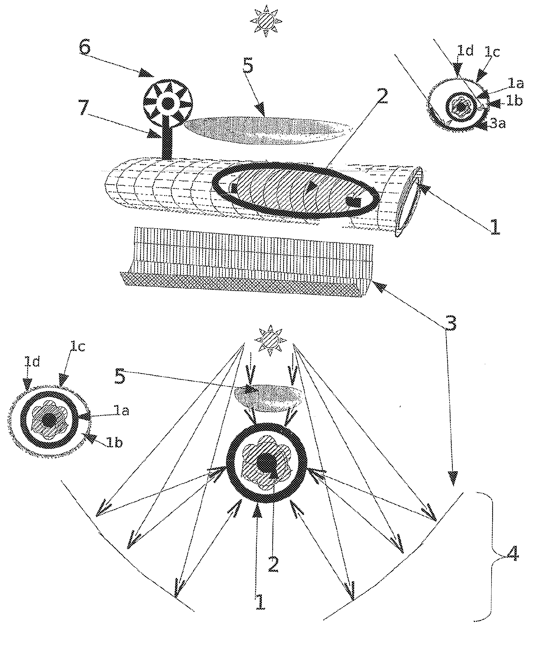
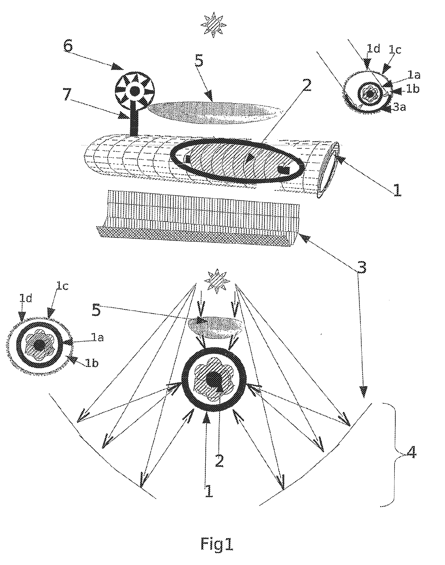
[0067]1.1 In one embodiment, the functional unit enabling torrefaction and pyrolysis of the substrate is a solar / microwave oven reactor (F_smo) consisting of a pipe (FIG. 1.1) with a diameter of between 1 centimeter and 5 meters and a length of between 10 centimeters and 10 meters. The pipe will be, for example, made of a refractory material such as (but not limited to) carbon covered with ceramic, ceramic, tungsten steel, titanium, nickel and so on.

[0068]At the center of the pipe, a worm screw (FIG. 1.2) is provided, enabling the biomass or the coal to move through the opening of the pipe. The substrate may be organized in homogeneous or non-homogeneous granules or particles with a size between several millimeters to several centimeters. In this document, granules and particles will be referred to as granules. Outside the pipe at a constant distance, along the length thereof, one or more mirrors or solar concentrators are provided, for example aluminum (FIG. 1.3), enabling the ligh...


PUM


Abstract

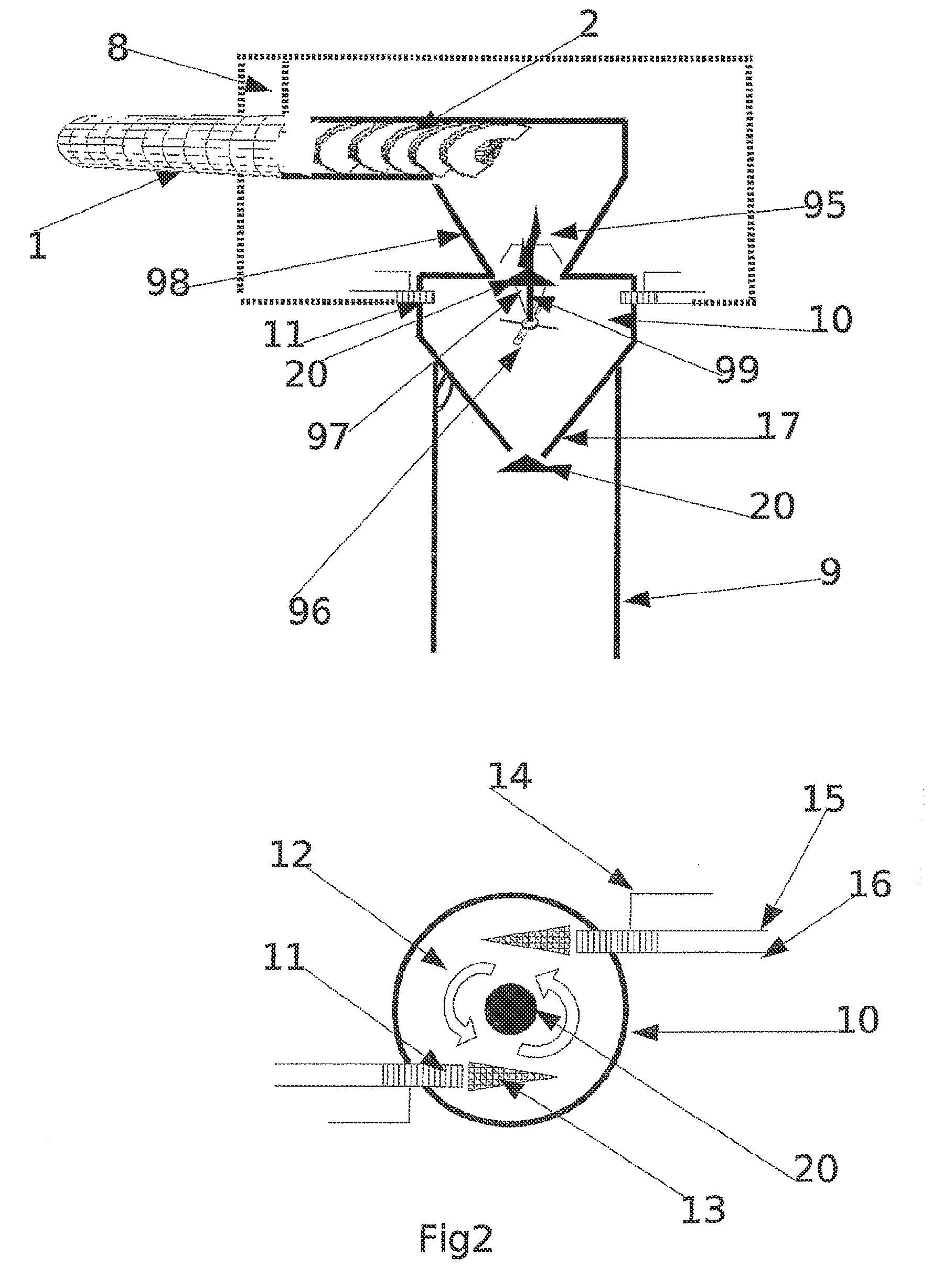
A system uses thermal solar energy coupled with microwaves and plasma for producing carbon monoxide (CO) and dihydrogen (H2) from carbonated compounds (biomass, domestic waste, sludge from waste water, fossil coal), wherein the obtained gaseous mixture yields, amongst others, hydrocarbon fuels (olefins, paraffin), esters, and alcohols via a Fischer-Tropsch synthesis. In a first step the carbonated compounds are roasted and pyrolized to produce char and dry coal, and a mixture of superheated gases containing CO2, steam, tars and non-condensable volatile materials. The method includes in a second step, and from the pyrolyis products (char or coal, gas mixture), generating a syngas substantially containing a mixture of carbon monoxide and dihydrogen, the mixture being used in Fischer-Tropsch synthesis units. After the Fischer-Tropsch step, the synthesis products are separated in a distillation column after heating in solar furnaces of mixed furnaces (solar / microwave).

Description

BACKGROUND OF THE INVENTION[0001]The exhaustion of petroleum resources and the carbon dioxide (CO2) pollution produced by burning petroleum products (one of the main causes of global warming) make it necessary to develop less polluting alternative energy production processes, enabling the quality of life in industrialized countries to be preserved and the ever-increasing need for energy in emerging countries to be addressed. Indeed, the global energy consumption was 5500 Mtoe in 1971, 10300 Mtoe in 2002 and is estimated to be at 16500 Mtoe in 2030.[0002]It is necessary, however, to distinguish:[0003]energy requirements intended for industrial and urban development, which can be qualified as static (for which numerous solutions are emerging (essentially, solar, nuclear, hydraulic, geothermic and wind power production); from[0004]energy requirements related to transportation, which require storage and transport of energy by the actual vehicle, with the exception of electric track vehi...

Claims


Application Information

Patent Timeline
IPC IPC(8): A62D3/178B01J19/08F24S20/30
CPCB01J8/0055Y02T50/678B01J19/088B01J19/10B01J19/126B01J19/127B01J19/129B01J19/18B01J19/1806B01J19/20B01J19/2405B01J19/26B01J2208/00884B01J2219/0809B01J2219/0815B01J2219/082B01J2219/0826B01J2219/0828B01J2219/083B01J2219/0833B01J2219/0841B01J2219/0852B01J2219/0854B01J2219/0856B01J2219/0858B01J2219/086B01J2219/0866B01J2219/0867B01J2219/0869B01J2219/0871B01J2219/0879B01J2219/0892B01J2219/0896B01J2219/0898B01J2219/1215B01J2219/1227B01J2219/1239B01J2219/1242B01J2219/1245B01J2219/1266B01J2219/1269B01J2219/1272B01J2219/1284B01J2219/1296B01J2219/185B01J2219/1943C10B19/00C10J3/487C10J3/66C10J2300/0916C10J2300/094C10J2300/1284C10J2300/16C10L9/083Y02E50/15Y02E60/364B01J8/44Y02P20/145Y02E50/10Y02E60/36Y02P20/133
Inventor UGOLIN, NICOLAS
Owner UGOLIN NICOLAS
Learn More