Optical Network for Cluster Computing

a cluster computing and optical network technology, applied in the field of optical networks and cluster computing, can solve the problems of limited transmission speed, high installation and management cost of conventional systems, and ultimately limited scalability of these systems

Active Publication Date: 2010-10-07
SANDISK TECH LLC
View PDF4 Cites 42 Cited by
  • Summary
  • Abstract
  • Description
  • Claims
  • Application Information

AI Technical Summary

Problems solved by technology

The scalability of these systems is ultimately limited by the reach of the copper cabling, which at high transmission speeds is restricted.
These conventional systems can suffer from high cost of installation and management due to the complex configuration of copper cabling.
The density of the system is limited by the connector density at the nodes of the leaf elements, as well as the high power required to drive high bandwidth signals through the relatively high signal loss cabling.
The reliability is also reduced because the weight of the cables strains the connectors, resulting in faulty links which are difficult to isolate and replace.

Method used


Image

  • Optical Network for Cluster Computing
  • Optical Network for Cluster Computing
  • Optical Network for Cluster Computing

Examples


Embodiment Construction

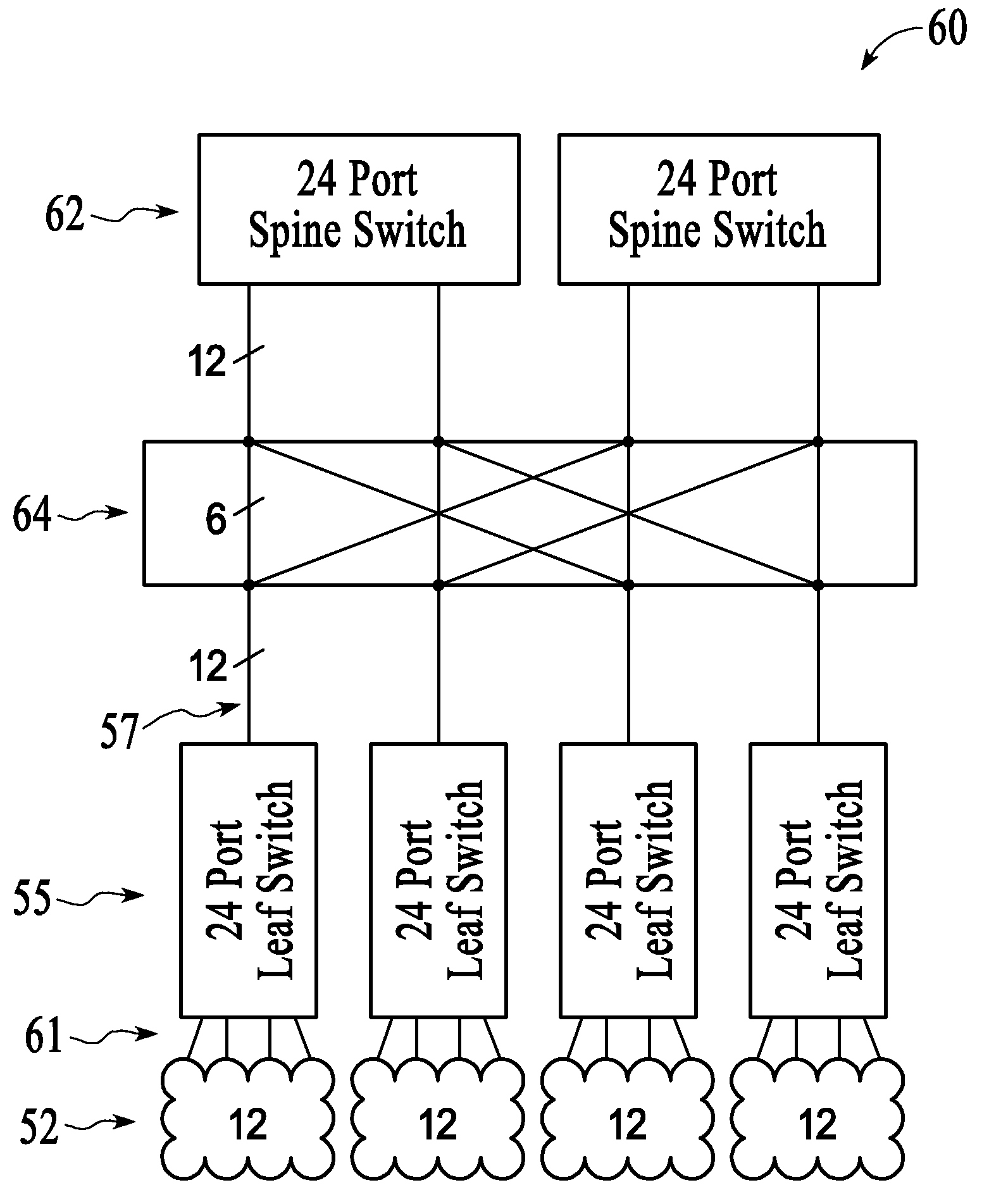
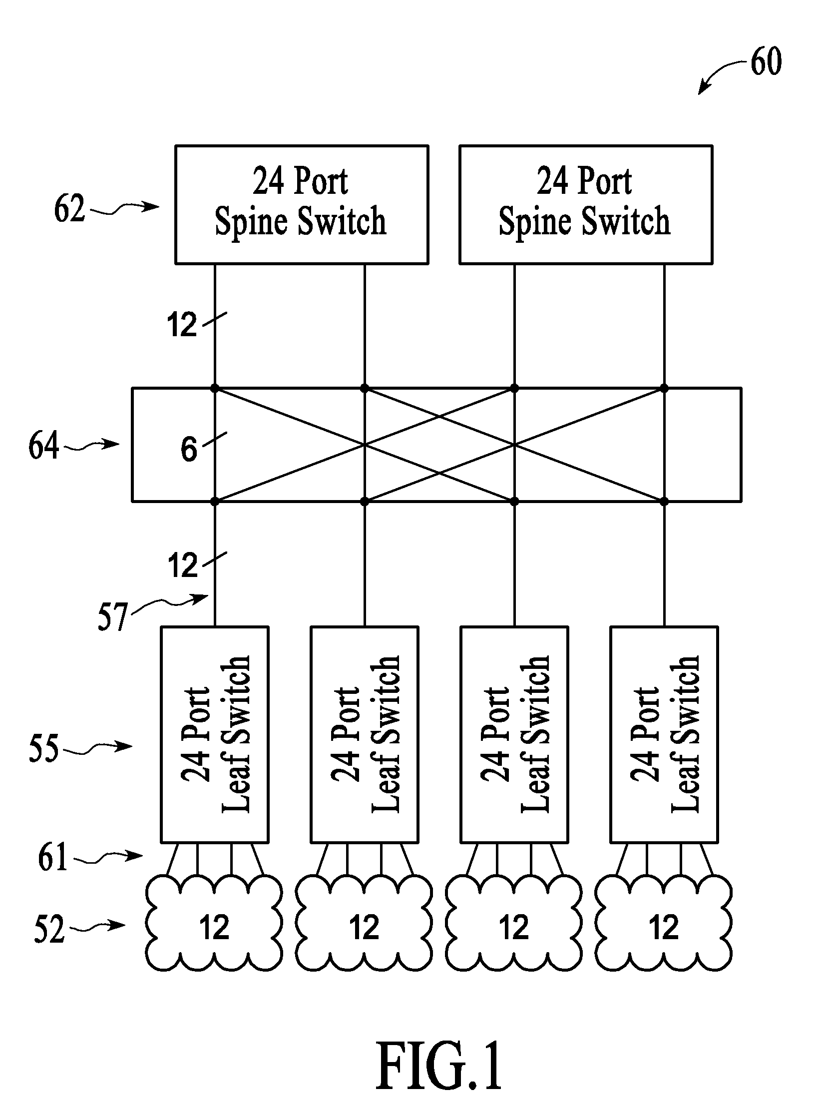
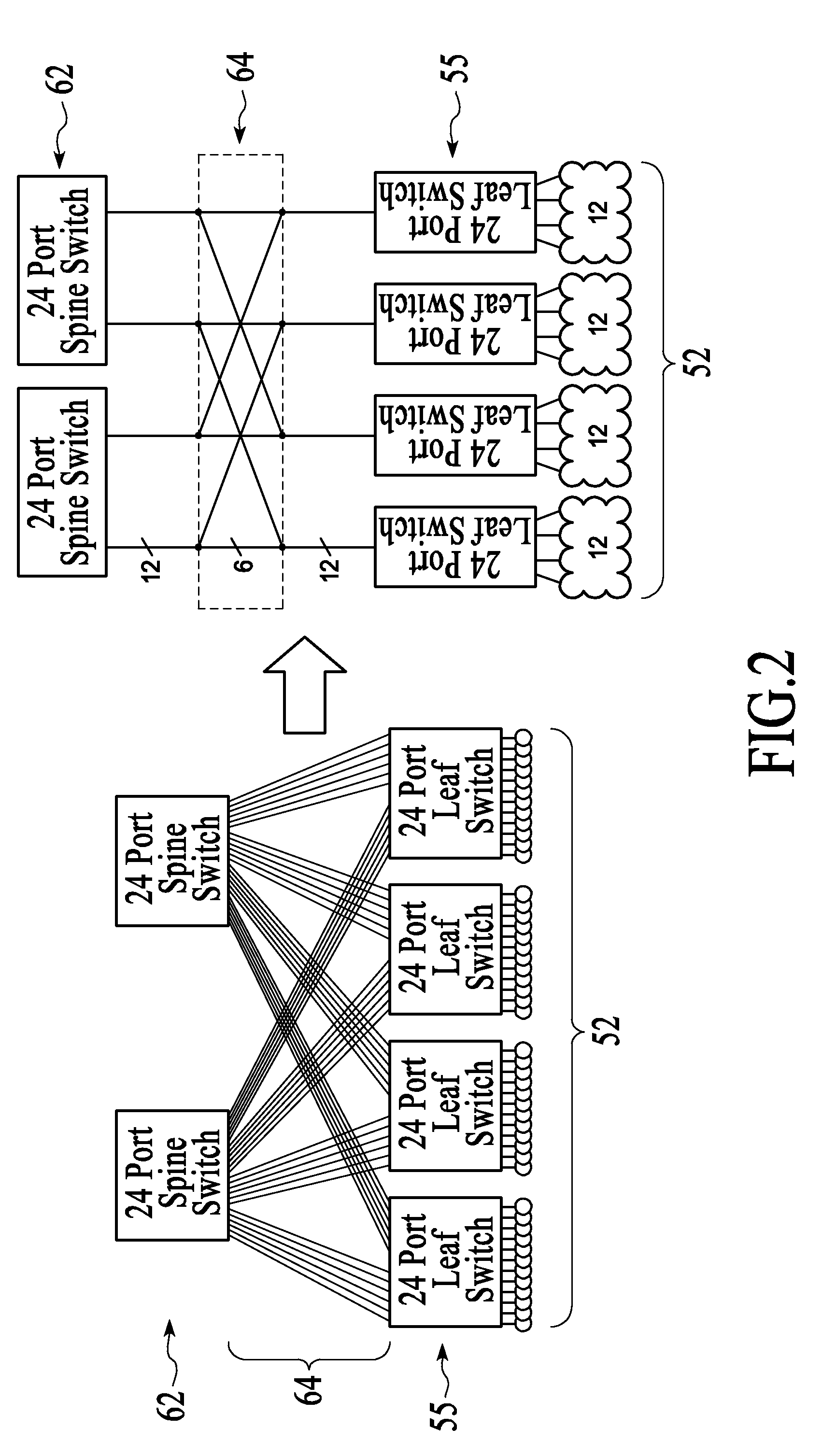
[0017]Embodiments of a multi-node optical computing cluster are described below. The multi-node optical computing cluster, also referred to herein as a cluster or optical computing cluster, provides numerous computing nodes connected to leaf ports in a two-stage network with a folded Clos topology. The network includes any number of nodes (e.g., 48, 96, 288, etc.) and further scaling is possible under the embodiments herein, for example, clusters using the network structure of an embodiment can be built having thousands of nodes. Furthermore, the network has full bisectional bandwidth. The network elements are distributed among the computing nodes, thereby allowing for aggregation of the network uplinks from the leaf switches to the spine switches. The denser uplinks allow for simplified cabling, and the node links and uplink ports share a common physical layer for flexibility in configuration. Consequently, the cluster network structure of an embodiment is scalable while maintainin...


PUM


Abstract

Leaf switches and spine switches in a Clos network are interconnected by optical fibers. The network enables large numbers of servers or other apparatus to communicate with each other with minimal delay and minimal power consumption.

Description

TECHNICAL FIELD[0001]The embodiments herein relate to optical networks and cluster computing, and in particular to switching networks for interconnecting any one of a large number of input nodes to any one of a large number of output nodes.BACKGROUND[0002]Crossbar switches are well known for providing arbitrary numbers of interconnections between input nodes and output nodes. Clos networks are often used for switching when the physical circuit switching needs exceeds the capacity of any reasonably feasible single crossbar switch. Clos networks employ stages of crossbar switches to interconnect the input nodes to the output nodes. An advantage of Clos networks is that the network can scale up in node count using crossbar switches of a fixed size, which is not possible in a single switch.[0003]Clos network topology (sometimes also known as a ‘Fat Tree’ topology) is often used in high performance computing clusters. The Clos structure provides constant bisectional bandwidth (the bandwi...

Claims


Application Information

Patent Timeline
Patent Type & Authority Applications(United States)
IPC IPC(8): G02B6/35H04J14/00
CPCH04Q2011/0052H04Q11/0005
Inventor KIRKPATRICK, PETER E.VERDIELL, JEAN-MARCEPITAUX, MARC
Owner SANDISK TECH LLC
Why Eureka
Try Eureka