Eureka AIR delivers breakthrough ideas for toughest innovation challenges, trusted by R&D personnel around the world.

Method for producing carbon nanotube-containing conductor

Active Publication Date: 2010-10-07
MEIJO NANO CARBON
View PDF14 Cites 45 Cited by
  • Summary
  • Abstract
  • Description
  • Claims
  • Application Information

AI Technical Summary

Benefits of technology

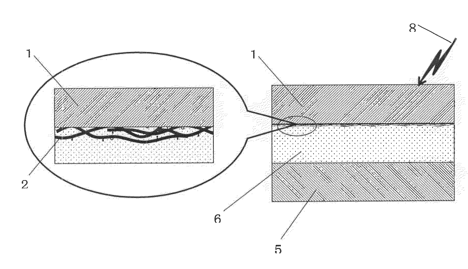
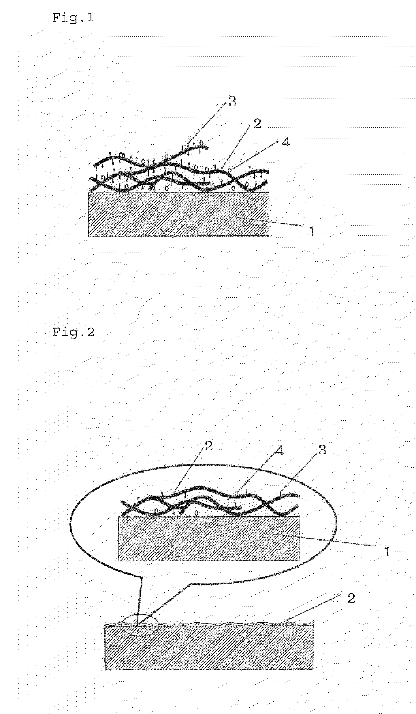
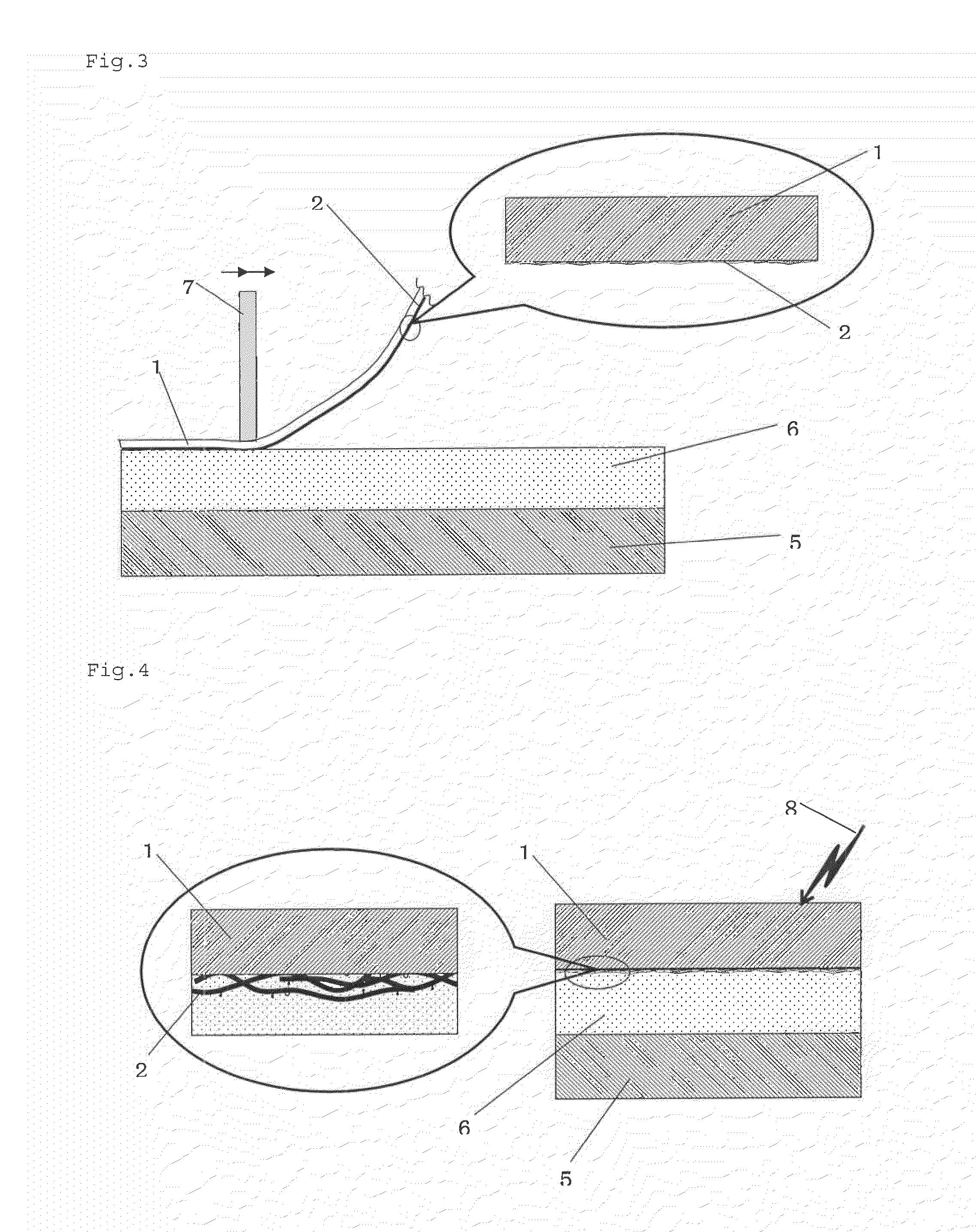
[0029]The method of the present invention makes it possible to obtain a carbon nanotube-containing conductor, in which a continuous three-dimensional network layer of carbon nanotubes is embedded and fixed in the extreme vicinity of the surface of an electron beam-curable resin layer provided on the surface of a transparent objective substrate that is a material to be given conductivity. According to the present invention, carbon nanotubes can be fixed in such a state that a continuous three-dimensional network layer thereof is embedded in the extreme vicinity of the surface of the electron beam-curable resin layer, without the binder resin or the like which does not always have a high conductivity adhering to or covering the surface of the individual carbon nanotube fibers. Accordingly, as compared with a conventional method such as coating with a carbon nanotube-containing coating material, the method of the present invention ensures extremely excellent conductivity. In addition, it provides a conductor extremely excellent in durability and film strength due to the structure where carbon nanotubes are embedded in a resin layer cured by electron beams such as UV rays.
[0030]Further, the thus-formed carbon nanotube-containing electron beam-curable resin layer has good light transmittance, and therefore, when a highly transparent one is used as the objective substrate, a conductor extremely excellent in transparency, especially a conductive transparent thin film can be obtained. Accordingly, in the objective substrate having an electron beam-curable resin layer containing a carbon nanotube network layer, which is obtained according to the method of the present invention, decrease in whole light transmittance relative to that of a non-processed one may remain at 10% or less, and a haze may be at most 1.0%.

Problems solved by technology

However, for these ITO sputtered films or ion-plated films, the production equipment must be extremely large-scaled, the size of the products and the producibility are limited, and the products are expensive.
What is worse, the obtained coated films are disadvantageous in that they are hard and brittle, and they have a problem of depletion and rise in the price of indium resources.
However, thickness of the conductive polymer layer is limited due to the color phase peculiar to conductive polymers, and in order to avoid the coloration problem, thickness of the layer must be greatly reduced to 0.2 μm or thinner, resulting in the undeniable lack of strength of the coating film.
The conductive polymer has an unsaturated bond derived from the molecular structure thereof, and has the essential drawback of deterioration by UV rays or the like, leading to a serious limitation in practical long-term use as an optical film.
However, since these carbon nanotubes are produced in aggregate form in which from tens to hundreds ultrafine single fibers are mutually entangled, regardless of whether the single-walled or multi-walled structure, it is extremely difficult to discretely disperse these single fibers in a solvent or a resin.
This is one of the major technical obstacles to development of application of carbon nanotubes.
However, the dispersion extremely easily reaggregates owing to the morphology and the surface property of carbon nanotubes, and is poor in storage stability.
Further, when a dispersion liquid comprising carbon nanotubes and a dispersing solvent is directly applied onto an objective substrate, the adhesiveness thereof to the objective substrate is poor, the mechanical strength of the coating film is low, and the film is not practicable.
However, since these resin binders and dispersants are generally electrically-insulative, they do not provide surface resistivity as low as expected to a carbon nanotube-containing coating film formed by applying a carbon nanotube-containing coating material onto an objective substrate and drying it thereon.
There is an attempt to improve the conductivity of the coating film by increasing the carbon nanotube content thereof, however, surface resistivity of the resulting coating film can only be improved in some degree at the expense of transparency.
However, in fact, the coating film could not satisfy both high transparency (for example, a whole light transmittance of at least 85%) and high conductivity (for example, a surface resistivity of at most 105 Ω / square) required in an optical film and the like, because the UV-curable resin component is naturally electrically-insulative.
However, this cannot improve the conductivity as much as expected and has the intrinsic drawbacks attributed to conductive polymer as described above, and thereby fails to exhibit a synergistic effect of carbon nanotubes and conductive polymer.
However, this still could not exhibit a synergistic effect capable of solving the above-mentioned problems attributed to metal oxide (for example, Patent Document 11).
However, these methods are still unsatisfactory for optical use in which both high transparency (for example, a whole light transmittance of at least 85%) and high conductivity (for example, a surface resistivity of less than 104 Ω / square) is indispensable, and films having sufficient strength and durability could not be produced.
However, the method has practical problems in mechanical strength and durability of the film, because the binder resin layer is too thin.

Method used


Image

  • Method for producing carbon nanotube-containing conductor
  • Method for producing carbon nanotube-containing conductor
  • Method for producing carbon nanotube-containing conductor

Examples


example 1

(1) Formation of Release Substrate Having Carbon Network Layer

[0098]0.10 parts of SWNT FH-P (mean diameter: 2 to 3 nm, aspect ratio: 1000 to 5000, produced by Meijyo Nano Carbon) as single-walled carbon nanotubes and 0.60 parts of sodium alkylbenzenesulfonate (trade name: Neopelex G-65, produced by Kao) as a dispersant were added to 99.30 parts of water, and the mixture was dispersed using an ultrasonic disperser (trade name: UH 600, produced by SMT) set at an output power of 7, at a cooling water temperature of 10° C. The dispersion time was about 30 minutes when the mixture amount was 100 g. Next, 0.50 parts of polyether-modified polydimethylsiloxane (trade name: BYK 348, Produced by BYK Chemie) as a leveling agent was added to the ultrasonicated dispersion with stirring to prepare a dispersion for carbon nanotube network layer formation.

[0099]Subsequently, the dispersion for carbon nanotube network formation was applied onto a release substrate, UV-transmissive untreated PET film...

example 2

Physical Data Comparison in Change of Carbon Nanotube (CNT) Coating Amount

[0107]Objective substrates having a carbon nanotube-containing resin coating layer were produced under the same condition and according to the same operation method as in Example 1, except that the carbon nanotube coating amount was changed as shown in Table 3.

[0108]The CNT coating amount was a computed amount obtained according to the following formula:

Wet thickness with bar coater: Tw (μm)

Density of dispersion for carbon nanotube network layer formation:

G (g / cm3)

CNT concentration in dispersion for carbon nanotube network layer formation: C %

[0109]Table 3 also shows the physical data of these objective substrates which were evaluated in the same manner as in Example 1.

[Formula 1]

[0110]CNT coating amount (g / m2)=(Tw×G×C) / 100

TABLE 3Experiment 2Experiment 3Experiment 4Experiment 5CNT coating amount (g / m2)6.9 × 10−39.2 × 10−323.0 × 10−334.5 × 10⁻³Surface resistivity (Ω / square)2.3 × 10⁵ 7.8 × 10⁴  9.5× 10³ 4.2 × 10...

example 3

Comparison in Drying Temperature in Carbon Nanotube Network Formation

[0112]Objective substrates of acryl plate having a carbon nanotube-containing resin coating layer were produced according to the same operation method as in Example 1, except that the drying temperature of 130° C. and the drying time of 1 minute after the bar coater coating with the aqueous solution for carbon nanotube network formation in (1) of Example 1 were changed as shown in Table 4.

[0113]Table 4 also shows the physical data of these objective substrates which were evaluated in the same manner as in Example 1.

TABLE 4Experiment 6Experiment 7Experiment 8Experiment 9Experiment 10Drying temperature (° C.)1101201506030Drying time (min)1 min1 min1 min3 min1 minSurface resistivity (Ω / square)2.3 × 1042.5 × 1042.7 × 1042.6 × 104*Whole light transmittance (%)87.687.687.387.5*Haze0.40.40.40.4*Pencil hardness5H5H5H5H*Adhesivenessclass 0class 0class 0class 0** Under the condition of 30° C. × 1 minute (Experiment 10), wate...


PUM


Abstract

The invention is to provide a method for producing an inexpensive carbon nanotube-containing conductor having high transparency and high conductivity as well as excellent durability. The invention is a method for producing a carbon nanotube-containing conductor having a conductive layer on the surface of an objective substrate, and the method includes the steps of pressing a release substrate having a carbon nanotube network layer, via the carbon nanotube network layer thereon, against a transparent objective substrate coated with an electron beam-curable liquid resin composition to infiltrate the liquid resin composition into the carbon nanotube network layer; irradiating it with electron beams to cure the liquid resin composition; and peeling away the release substrate to obtain an objective substrate having a resin composition layer with carbon nanotubes embedded in the surface thereof. According to the invention, a conductor and a conductive film having high conductivity and transparency as well as excellent strength and durability are obtained.

Description

TECHNICAL FIELD[0001]The present invention relates to a method for producing an inexpensive carbon nanotube-containing conductor excellent in conductivity, transparency and durability. More precisely, the invention relates to a method for producing an inexpensive carbon nanotube-containing transparent conductor which combines incompatible properties such as inexpensiveness, high flexibility and durability, high transparency, and high conductivity.BACKGROUND ART[0002]In flat panel displays such as liquid crystals and organic EL, a high-conductive film having high transparency is much used. At present, the prevailing products are transparent films of polyethylene terephthalate (PET) or the like coated with a conductive metal oxide such as indium tin oxide (ITO) by vapor deposition or sputtering. However, for these ITO sputtered films or ion-plated films, the production equipment must be extremely large-scaled, the size of the products and the producibility are limited, and the product...

Claims


Application Information

Patent Timeline
IPC IPC(8): B44C1/175
CPCB82Y30/00B82Y40/00C01B31/0273C01B2202/02C01B2202/06Y02E10/549C01B2202/34C01B2202/36H01B1/24H01L51/444C01B2202/28C01B32/174Y02P70/50H10K30/821H01B13/00
Inventor MORIMOTO, YOSHIYUKIKUBOSAKI, NOBUONAKAMURA, NORIYUKISUMITA, YUZO
Owner MEIJO NANO CARBON
Why Eureka
Eureka Blog
Learn More