
Apparatus for moulding a part of a packaging container

a packaging container and moulding device technology, applied in the direction of turning apparatus, containers, shaping press rams, etc., can solve the problems of difficult to achieve balance in the moulding apparatus, external disruption, and short production cycle time of this type of injection moulding which takes place in the packing and filling machine, so as to improve the stability of the moulding apparatus and the degree of accuracy

Active Publication Date: 2010-09-30
TETRA LAVAL HLDG & FINANCE SA
View PDF5 Cites 8 Cited by
  • Summary
  • Abstract
  • Description
  • Claims
  • Application Information

AI Technical Summary

Benefits of technology

[0013]One object of the present invention is therefore to propose an apparatus for moulding a thermoplastic package part in association with an end portion of a packaging container body, which package part can be produced with a high degree of accuracy thanks to improved stability in the moulding apparatus.
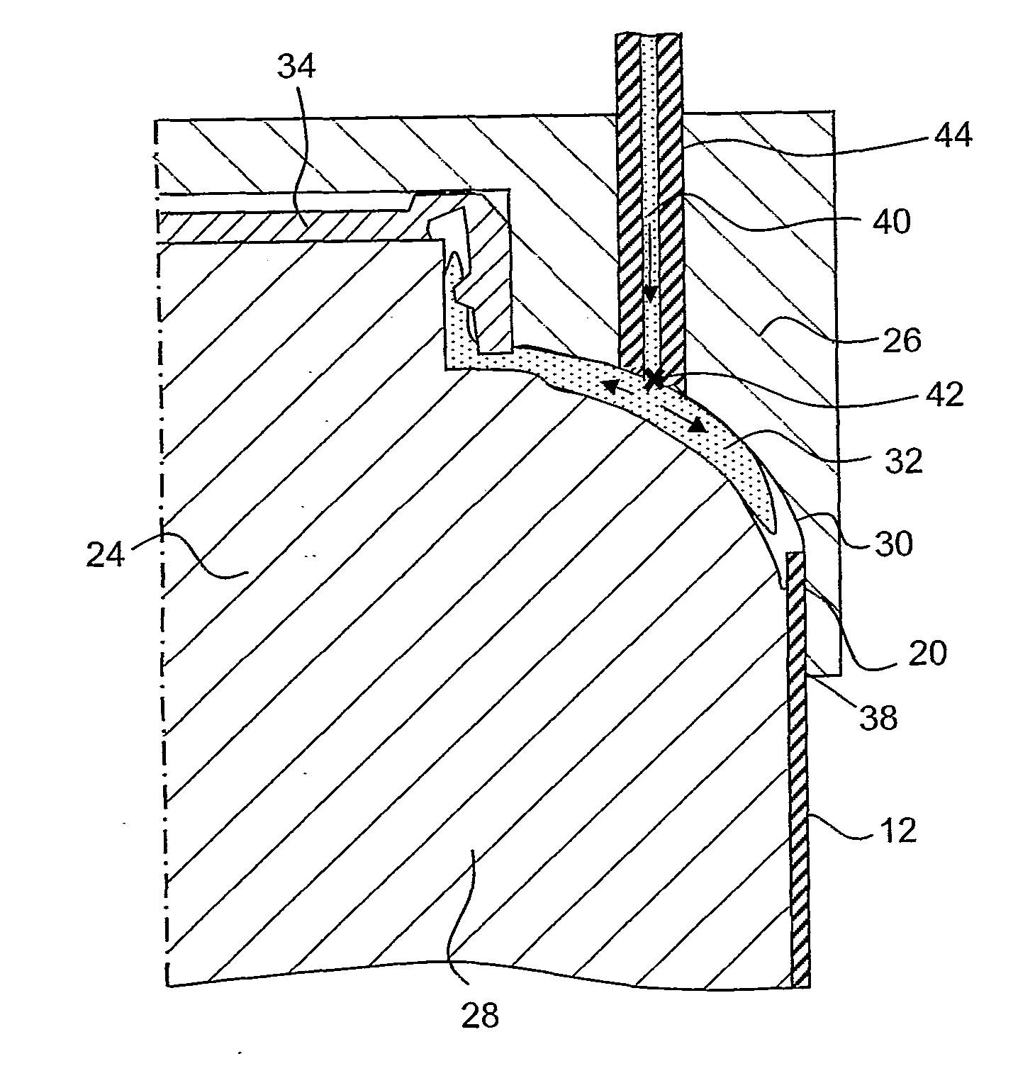
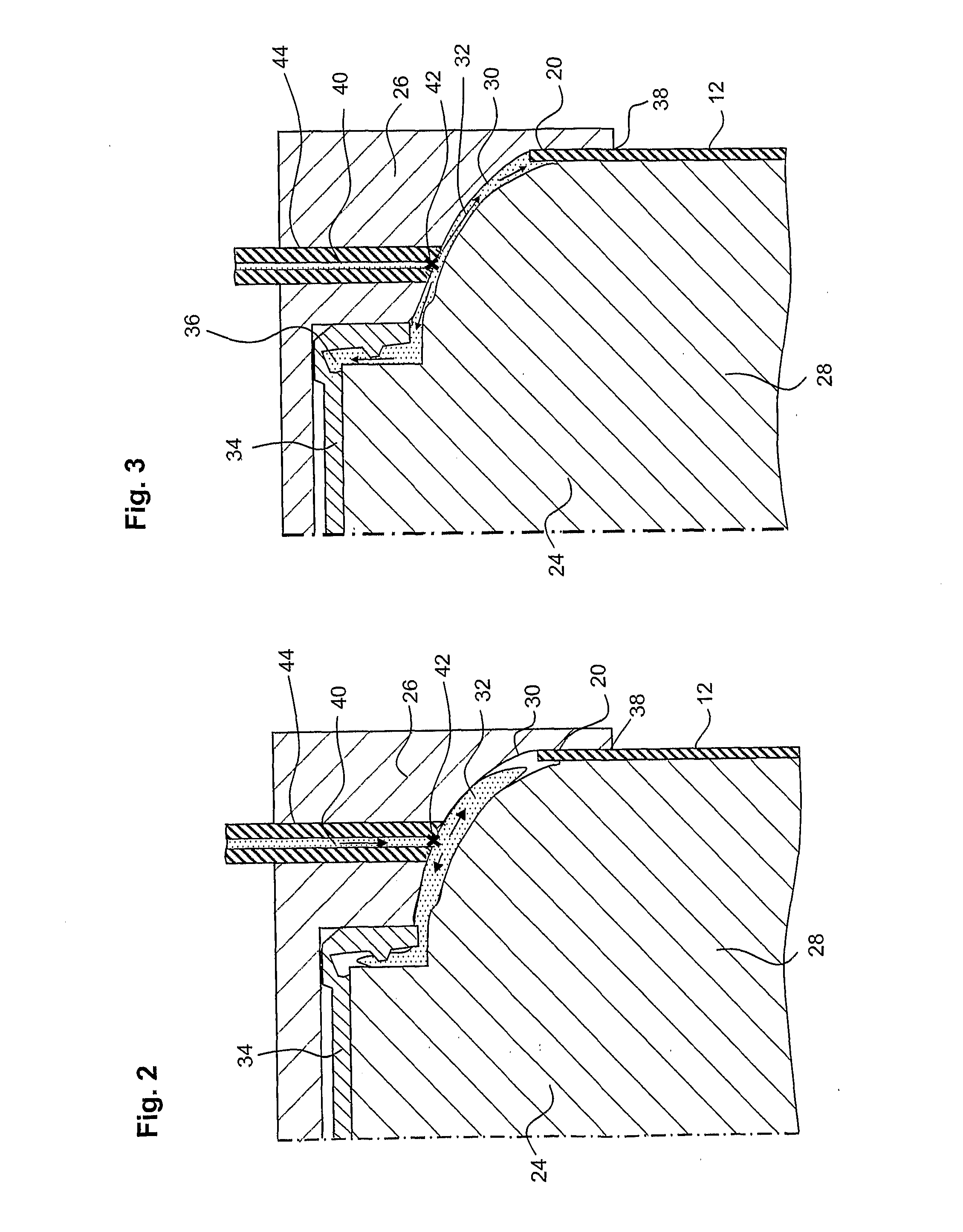
[0015]The partly free suspension of at least one of the mould elements implies a possibility for the apparatus to realise greater stability and greater immunity to disruptions. If melt is injected into the cavity in a number of points, and slightly more melt enters at one point than the other points, the apparatus can compensate for this if said force centre may be caused to pass through a surface which is defined in the above mentioned manner, the surface being contiguous and continuous. When the mould elements are then compressed together, there will initially be a greater pressure in the larger quantity of melt and the movable mould element adjusts itself accordingly. However, the cavity strives to create a power balance and the compression force entails that the greater quantity of melt is spread out over a larger area than the smaller quantities of melt. As a result, the difference in pressure in the different melts is ultimately substantially zero, and the movable mould element adjusts itself accordingly. The material thickness of the moulded thermoplastic package part will thereby be more or less uniform.
[0020]In one currently preferred embodiment, the apparatus according to the present invention includes means for converging the mould elements so that the cavity is partly closed before the plastic melt is injected, and the plastic melt is injected into the cavity through ducts, each of which ducts being in its one end in communication with an extruder and in its other end discharges in the cavity in one of said points. This technology is entitled, as was mentioned previously, injection compression and gives a very good result on moulding of above all thin-walled package tops.
[0026]In still a further currently preferred embodiment of the present invention, the cavity is disposed also to be able to receive an opening device in the form of a cap, the cap together with a part of the inner mould element being disposed to form a neck of said package top which defines said pouring opening. By positioning a cap, for example a screw cap, in the cavity it is possible for the packaging top to be moulded against the cap, which gives an opening device which is extremely simple to handle for the consumer, but which, before opening, is nevertheless extremely tight and leakproof.
[0027]One currently preferred embodiment of the present invention is characterised in that the at least partly free suspension implies that at least one of the mould elements is suspended via a resilient element, and that the compression force can thereby be restricted somewhat. By such means, the apparatus is capable of balancing out any possible oblique guiding of the mould elements as well as possible distorted distribution of the plastic melt over each respective injection point.

Problems solved by technology

The package parts which are injection moulded are of thin-walled material and the production cycle time for this type of injection moulding which takes place in a packing and filling machine is extremely short compared with normal injection moulding.
However, despite the symmetry it may be difficult to attain balance in the moulding apparatus, i.e. to cause the flow front of the plastic melt to move uniformly everywhere before the plastic melt has time to harden anywhere.
External disruptions may easily give rise to instability.
Such disruptions may, for example, be uneven control of the moulding tools or changes in the quantity of plastic melt at any point or in the composition of the plastic melt proper.
It has however proved that this solution per se is insufficient to achieve optimum moulding, but there is room for improvement as regards balancing of the mould.

Method used


Image

  • Apparatus for moulding a part of a packaging container
  • Apparatus for moulding a part of a packaging container
  • Apparatus for moulding a part of a packaging container

Examples


Embodiment Construction

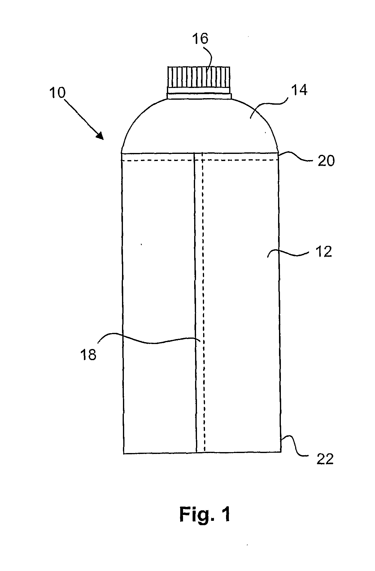
[0044]The present invention is applicable in the manufacture of, for example, such a packaging container as is illustrated in FIG. 1, and which hereinbelow will be given reference numeral 10. Said packaging container 10 comprises a body 12 in the form of a sleeve of packaging laminate and a thermoplastic package part in the form of a thin-walled top 14. On the top 14 a neck with a pouring opening is arranged (not shown), and this pouring opening is provided with an opening device 16 in the form of a cap which, in this example, consists of a screw cap with threads on the inside which engage with threads on the outside of the neck.

[0045]The sleeve 12 is manufactured in that two longitudinal edges of a sheet of packaging laminate are caused to form an overlap joint 18 which is sealed. The packaging laminate may be of a multiplicity of types, but normally comprises a core layer of paper or paperboard and one or more barrier layers of, for example, plastic and aluminium foil. In this exa...


PUM

PropertyMeasurementUnit
Forceaaaaaaaaaa

Abstract

An apparatus for moulding a thermoplastic package part(s) to an end portion of a container body includes inner and outer mould elements between which a mould cavity per package part is formed. At least one of these mould elements is at least partly freely suspended. When one package part is moulded with the mould elements, plastic melt is injected in a first number ≧1 of points in the cavity, an island of plastic melt for each point is formed inside the cavity, and the distribution of the points causes a force centre to pass through a surface defined by a parallel projection of each first number of islands on a plane orthogonal to a direction of the compression force, and when the first number >1, a second number of imaginary straight lines interconnecting a third number of parallel projections such that the surface is at its maximum.

Description

TECHNICAL FIELD[0001]The present invention relates to an apparatus for moulding a part of a packaging container, in particular for moulding a top of thermoplastic on the edge of a sleeve of paper laminate.BACKGROUND ART[0002]The present invention has been developed to be employed in the moulding of thermoplastic package parts directly on other package parts, such as for example the moulding of a thermoplastic package top on a sleeve of packaging laminate including a core layer of paper. The package top may, in addition to being moulded against the sleeve, also be moulded against an opening device in the form of a cap, for example a screw cap.[0003]The result will be a packaging container in which food may be packed. The Applicant markets similar types of packages under, for example, the registered trademark Tetra Top®.[0004]Such a packaging container is manufactured today in that a flat-laid, tube shaped blank of a packaging laminate is raised and sealed in its one end in that a top...

Claims


Application Information

Patent Timeline
IPC IPC(8): B29C45/10
CPCB29C33/08B65D15/08B29C43/36B29C45/0046B29C45/045B29C45/14336B29C45/14467B29C45/14598B29C45/14754B29C45/66B29C2043/189B29C2043/3444B29C2043/3628B29C2043/522B29C2045/1792B29K2105/258B29L2001/00B29C2045/0027B29C43/18B29C43/04B29C45/04B29C45/08B29C45/56
Inventor ANDERSSON, PAR
Owner TETRA LAVAL HLDG & FINANCE SA
Learn More