Method of producing a fine grain casting

Inactive Publication Date: 2010-09-23
UNITED TECH CORP
View PDF18 Cites 13 Cited by
  • Summary
  • Abstract
  • Description
  • Claims
  • Application Information

AI Technical Summary

Benefits of technology

[0005]A disclosed induction heated furnace assembly for producing a directionally solidified casting includes a susceptor t

Problems solved by technology

Disadvantageously, a minimum level of current is required to produce the heat required to maintain the metal in a molten state.
However, the levels required to maintain heat may not provide the desired strength of the magnetic field.

Method used


Image

  • Method of producing a fine grain casting
  • Method of producing a fine grain casting
  • Method of producing a fine grain casting

Examples


Embodiment Construction

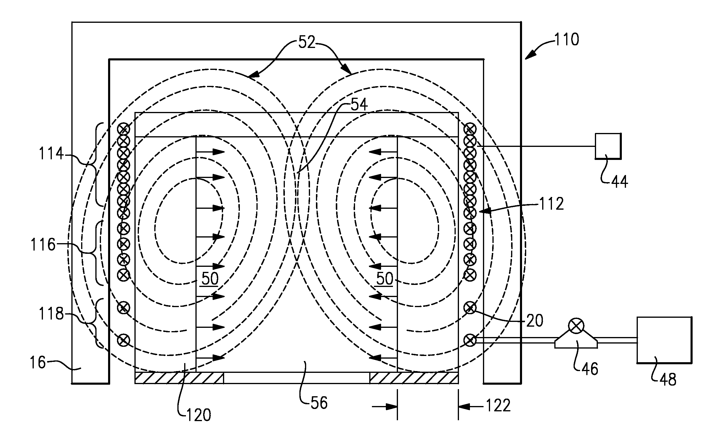
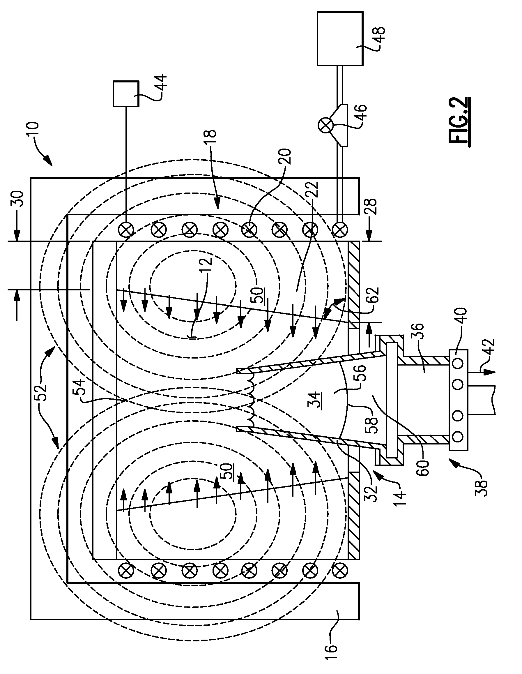
[0014]Referring to FIG. 1, an example induction furnace assembly 10 includes a chamber 12 that includes an opening 14 through which a mold 32 is received and withdrawn. The chamber 12 is isolated from the external environment by insulated walls 16. An inductive coil 18 generates heat, indicated by arrows 50, to maintain metal 34 within the mold 32 at a desired temperature.

[0015]The example furnace assembly includes a susceptor 22 that blocks a portion of a magnetic field (schematically shown at 52) that is generated by the inductive coil 18. The example susceptor 22 is a wall that surrounds the chamber 12 and is made of a graphite material. The susceptor 22 is fabricated from material such as graphite that blocks the penetration of the magnetic field 52 produced by the inductive coil 18. The susceptor 22 can also provide for the translation of energy from the magnetic field into heat energy, as indicated at arrows 50 to further maintain a temperature within the mold 32. In the discl...


PUM

PropertyMeasurementUnit
Thicknessaaaaaaaaaa
Diameteraaaaaaaaaa
Magnetic fieldaaaaaaaaaa

Abstract

An induction heated furnace assembly for producing a directionally solidified casting includes a susceptor that tailors strength of the magnetic field within the chamber to provide a desired grain structure in a completed cast part. The susceptor proportionally blocks portions of the magnetic field to provide different levels of magnetic stirring within the molten material at different locations within the furnace assembly stirring induced by the magnetic field is controlled and varied throughout the furnace assembly to create the desired grain structures in the completed cast article.

Description

BACKGROUND OF THE INVENTION[0001]This disclosure generally relates to a method and device for directional solidification of a cast part. More particularly, this disclosure relates to a directional solidification casting process that varies magnetic stirring to provide a desired grain structure.[0002]A directional solidification (DS) casting process is utilized to orientate grain structure within a cast part. The desired orientation is provided by moving a mold from a hot zone within a furnace into a cooler zone at a desired rate. As the mold moves into the cooler zone, the molten material solidifies along a solidification front in one direction.[0003]Mixing of the molten material within the furnace is known to produce a desired grain size. Such mixing can be induced in the molten metal material by a magnetic field generated from a coil encircling the furnace cavity. Typically, an induction furnace utilizes an electric coil that produces heat required for maintaining the metal in a m...

Claims


Application Information

Patent Timeline
IPC IPC(8): H05B6/22H05B6/36H05B6/34
CPCB22D27/045B22D27/02
Inventor BULLIED, STEVEN J.MARCIN, JOHN JOSEPHKENNARD CASTLE, LEA
Owner UNITED TECH CORP
Why Eureka
Try Eureka