
Polarizing plate, image display, and method of manufacturing polarizing plate

a technology of polarizing plates and image displays, applied in the direction of polarizing elements, instruments, synthetic resin layered products, etc., can solve problems such as polarization properties, and achieve the effects of high hardness, excellent adhesiveness, and high surface hardness

Inactive Publication Date: 2010-09-23
NITTO DENKO CORP
View PDF11 Cites 14 Cited by
  • Summary
  • Abstract
  • Description
  • Claims
  • Application Information

AI Technical Summary

Benefits of technology

[0007]Accordingly, the present invention is intended to provide a polarizing plate that has a high hardness, can have a reduced thickness, and has excellent polarization properties.
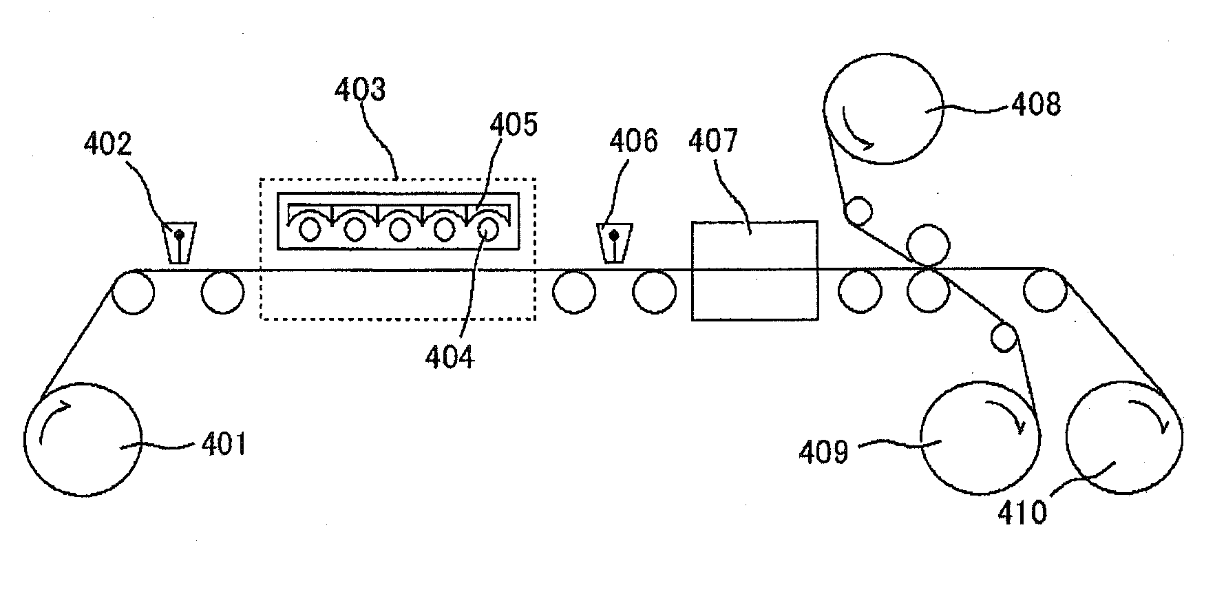
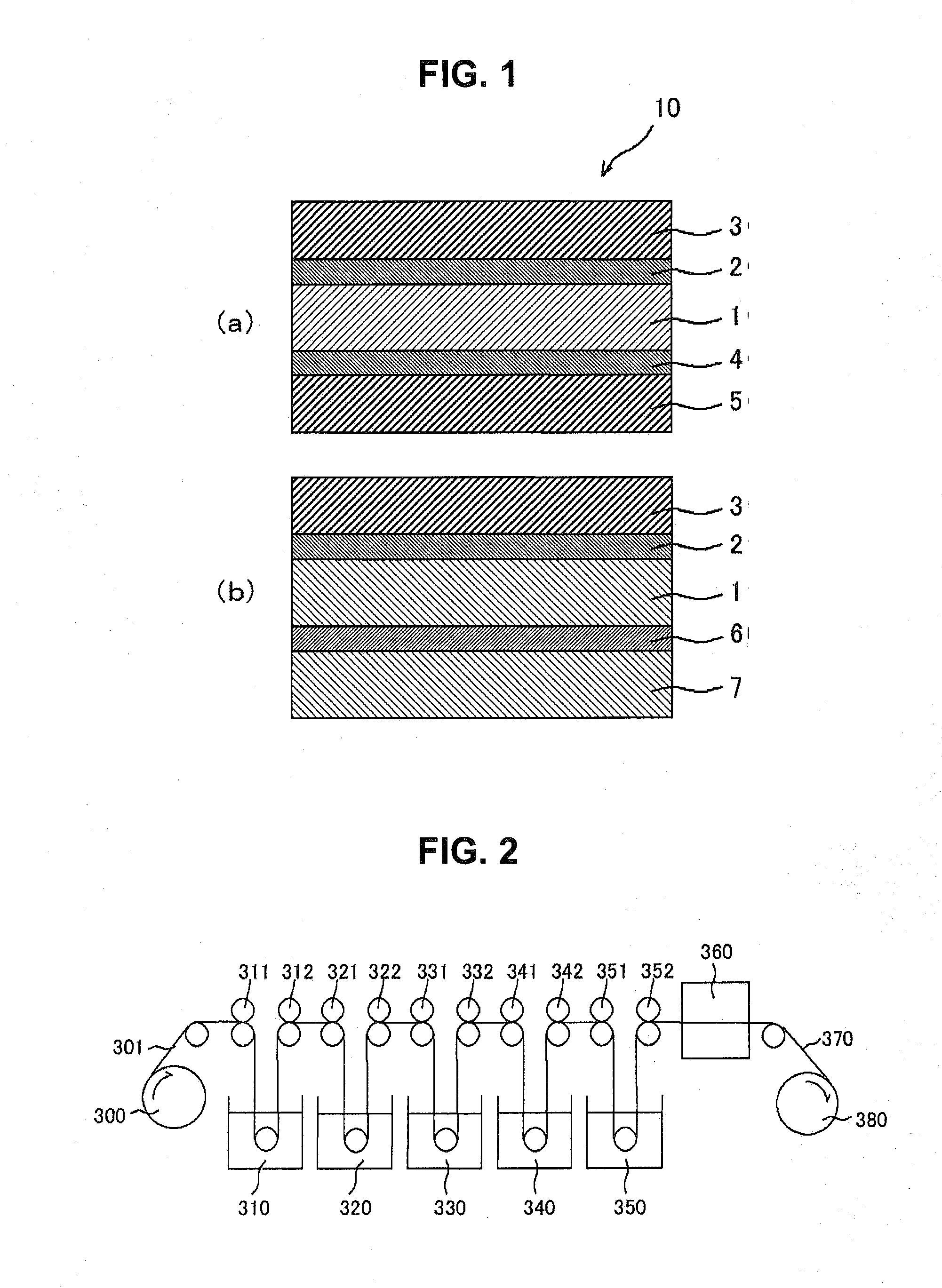
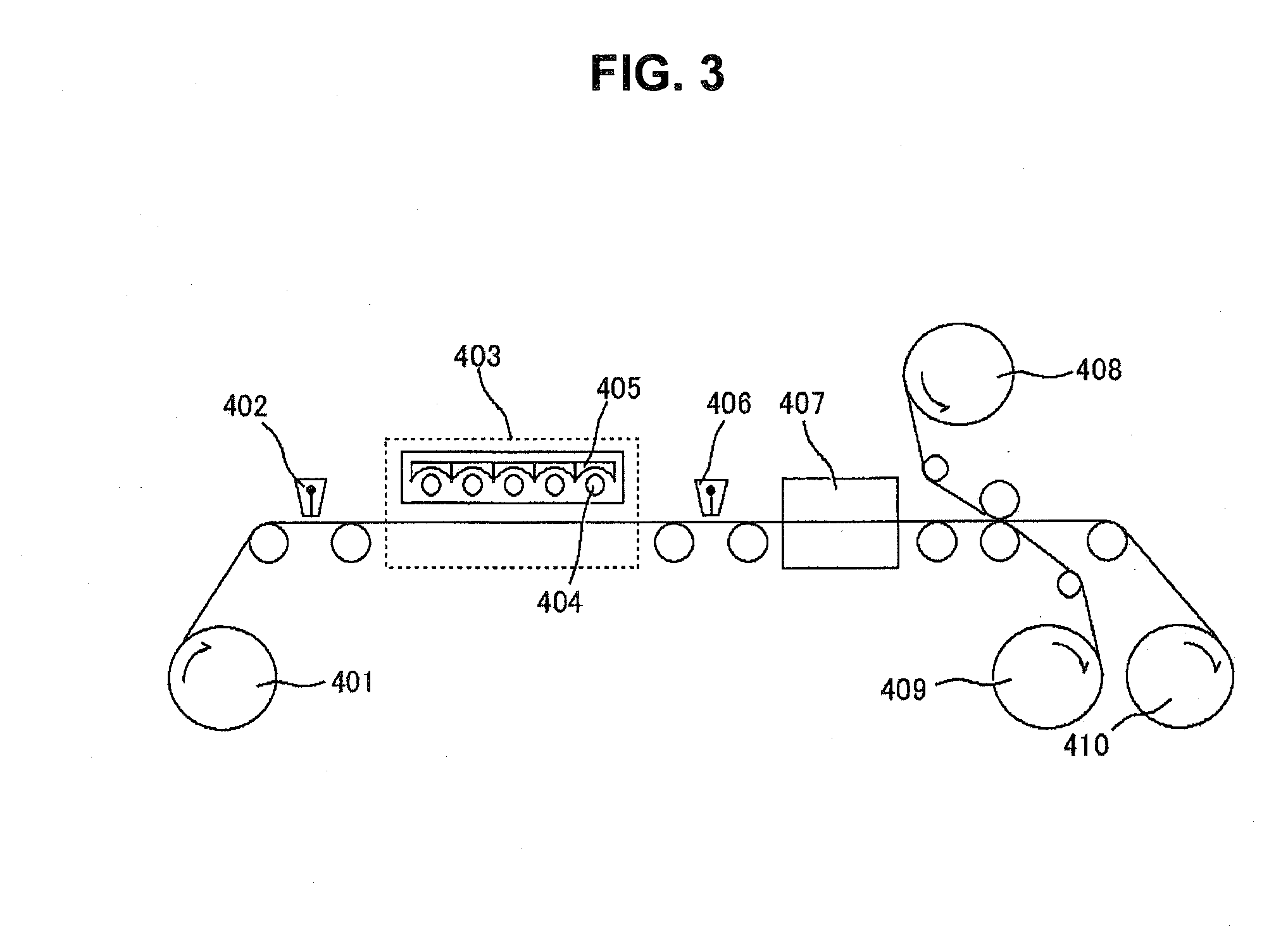
[0014]The present inventors made a series of studies with respect to the deterioration in properties of conventional polarizing plates in which a protective layer was formed directly on a polarizer using a photopolymerization compound. As a result, it was found that the deterioration in properties resulted from erosion of a polarizer caused by a solvent used for forming the protective layer in the conventional polarizing plates. Based on this finding, it was further found that when a cured resin layer was stacked on at least one surface of a polarizer, with an adhesive layer having a thickness in the range of 0.1 μm to 10 μm being interposed therebetween, using the solventless photocurable composition having the aforementioned composition, the properties of the polarizer were not deteriorated and a cured resin layer with a higher hardness than that of conventional hard-coating layers was formed. Thus the present invention was completed. In the polarizing plate of the present invention, since the thickness of the adhesive layer is in the aforementioned range, it has excellent adhesiveness between the polarizer and the cured resin layer as well as a higher surface hardness. That is, the thickness of the adhesive layer in the aforementioned range makes it possible to prevent the polarizer and the cured resin layer from being separated from each other, to improve the hardness of the cured resin layer, and to prevent cracks from being generated at the cured resin layer surface. Moreover, the polarizing plate of the present invention can have a reduced thickness since the protective layer can be omitted.

Problems solved by technology

Moreover, the polarizing plate wherein the TAC film is omitted and a protective film is formed on the surface of a polarizer using a photopolymerizable compound to reduce the thickness, has a problem with polarization properties.

Method used


Image

  • Polarizing plate, image display, and method of manufacturing polarizing plate
  • Polarizing plate, image display, and method of manufacturing polarizing plate
  • Polarizing plate, image display, and method of manufacturing polarizing plate

Examples


example 1

[0120]One surface of a polyethylene terephthalate film (with a thickness of 75 μm, “Lumirror S27-E” (trade name) manufactured by Toray Industries, Inc.) was coated with a solventless photocurable composition having the composition described below using a bar coater (#16). Thus a coating film was formed. Thereafter, the coating film was irradiated with ultraviolet rays whose wavelength was 365 nm using a high-pressure mercury lamp so that the accumulated light intensity was 300 mJ / cm2, and thereby a 22-μm thick cured resin layer was formed. Thus a first laminate (R1) was produced.

[0121]Component (A): 74 parts by weight of acrylic monomer (“KAYARAD DPHA” (trade name) manufactured by NIPON KAYAKU CO., LTD., Mw=578) represented by general formula (II) mentioned above

Component (B): 5 parts by weight of polyurethane acrylate (“SHIKOH UV-7600B” (trade name) manufactured by THE NIPPON SYNTHETIC CHEMICAL INDUSTRY CO., LTD.)

Component (C): 5 parts by weight of 1-hydroxy cyclohexyl phenyl keton...

example 2

[0128]A polarizing plate of this example was produced by the same method as in Example 1 except that coating with the adhesive composition was carried out using a bar coater (#10) and thereby a 2-μm thick adhesive layer was formed. The properties of this polarizing plate are indicated in Table 1 above.

example 3

[0129]A polarizing plate of this example was produced by the same method as in Example 1 except that the solventless photocurable composition and adhesive composition having the following compositions were used, the thickness of the cured resin layer was 20 μm, and the thickness of the adhesive layer was 2 μm. The properties of this polarizing plate are indicated in Table 1 above.

[0130]Component (A): 12 parts by weight of acrylic monomer represented by structural formula (II) described above (“DPHA” (trade name) manufactured by DAICEL-CYTEC Company, Ltd.)

Component (B): 16 parts by weight of aliphatic urethane acrylate (“PETIA” (trade name) manufactured by DAICEL-CYTEC Company, Ltd.)

Component (C): 24 parts by weight of urethane acrylate (“Shiko UV-7640B” (trade name) manufactured by Nippon Synthetic Chemical Industry Co., Ltd.)

Component (D): 14 parts by weight of methacrylate polymer (“ARONIX M9050” (trade name), Mw=3000, manufactured by TOAGOSEI CO., LTD.)

[0131]Aqueous polyurethane ...


PUM

PropertyMeasurementUnit
Lengthaaaaaaaaaa
Lengthaaaaaaaaaa
Thicknessaaaaaaaaaa

Abstract

A polarizing plate is provided that has high hardness, can have a reduced thickness, and has excellent in polarization properties. The polarizing plate includes a polarizer, an adhesive layer, and a cured resin layer. The adhesive layer is stacked on at least one surface of the polarizer. The cured resin layer is stacked on the surface of the adhesive layer located on the opposite side to the polarizer. The adhesive layer has a thickness in the range of 0.1 μm to 10 μm. The cured resin layer is formed of a solventless photocurable composition containing component (A) and component (B), with component (A) being at least one of a polyfunctional acrylic monomer and a polyfunctional methacrylic monomer and component (B) being a photocurable prepolymer.

Description

TECHNICAL FIELD[0001]The present invention relates to polarizing plates, image displays and method of manufacturing polarizing plates.BACKGROUND ART[0002]A liquid crystal display (LCD) is one of the various image displays available. An LCD is a device that displays, for example, letters and images using electrooptic properties of liquid crystal molecules. Generally, an LCD is provided with a liquid crystal cell and two polarizing plates disposed on both sides of the liquid crystal cell. Generally, the polarizing plates each have a structure in which a protective film is attached to both sides of a polarizer with an adhesive. Conventionally, a triacetyl cellulose (TAC) film is widely used as the protective film. Furthermore, the polarizing plates may be subjected to a hard-coating (hardening) treatment. The hard-coating treatment is carried out by forming a hard-coating layer on the TAC film using a photocurable resin. Commonly, one of the TAC films provided on both sides of the pola...

Claims


Application Information

Patent Timeline
IPC IPC(8): G02F1/1335G02B1/08B32B37/00B32B27/00
CPCG02B5/3033G02F1/133528Y10T428/265Y10T428/264G02F2201/50G02B5/30G02F1/1335
Inventor NAKANO, SHINYAOOE, NAOTO
Owner NITTO DENKO CORP
Learn More