Magnetic crystal for radio wave absorbing material and radio wave absorbent

Active Publication Date: 2010-09-23
THE UNIV OF TOKYO +1
View PDF12 Cites 33 Cited by
  • Summary
  • Abstract
  • Description
  • Claims
  • Application Information

AI Technical Summary

Benefits of technology

[0049]The most universal polymorphism of a composition of Fe2O3 having different crystal structures includes α-Fe2O3 and γ-Fe2O3, and also other iron oxides of FeO and Fe3O4. In production of the above-mentioned M-substituted ε-Fe2O3, the ε-Fe2O3 crystals may be in the form of a mixture with other iron oxide crystals (impurity crystals) that differ in point of the space group therebetween. The impurity crystals in the mixture may be acceptable within a range not interfering with the effect of the invention though they are unfavorable for making the M-substituted ε-Fe2O3 crystals exhibit their characteristics to a higher level.
[0050]According to the detailed investigations made by the present inventors, the trivalent M element capable of readily controlling the coercive force Hc of the M-substituted ε-Fe2O3 crystals depending on the degree of substitution with it includes Ga, Al and In. Using any of these elements as the substituent element M, the present inventors produced various M-substituted ε-Fe2O3 crystals at a different degree of substitution, and analyzed them for their magnetic properties. The substituted crystals are expressed as ε-MxFe2-xO3, and the value x (that is, the degree of substitution with M) and the found data of the coercive force Hc are shown in Table 3. The M-substituted ε-MxFe2-xO3 crystals of different compositions were produced according to the process shown in Examples given hereinunder. When Ga, Al, In or the like is selected as the substituent element M, the behavior of the M-substituted ε-MxFe2-xO3 crystals is that the coercive force Hc thereof lowers with the increase in the degree of substitution with M.
[0051]With the reduction in the coercive force Hc, the electromagnetic wave absorption peak is shifted to the lower frequency side (see FIG. 6 mentioned below). In other words, depending on the degree of substitution with the element M, the peak frequency of the electromagnetic wave absorption can be controlled. For example, the electromagnetic wave absorber packed with particles that comprise substituent element-free ε-Fe2O3 magnetic crystals as the magnetic phase (for example, having a thickness of from 2 to 10 mm) does not have an electromagnetic wave absorption peak within a detectable frequency region owing to the extremely large coercive force Hc of the magnetic particles (probably, it may have an electromagnetic wave absorption peak in a further higher frequency region); whereas the electromagnetic wave absorber packed with particles that comprise M-substituted ε-Fe2O3 magnetic particles as the magnetic phase, in which a part of Fe is substituted with a suitable amount of an M element to lower the coercive force Hc thereof, actually showed an electromagnetic wave absorption peak in a range of 140 GHz or lower. Ordinary magnetic oxides are such that their electromagnetic wave absorption becomes almost zero at a frequency remoter than the electromagnetic wave absorption peak frequency. As opposed to these, magnetic oxides comprising ε-Fe2O3 crystals or M-substituted ε-Fe2O3 crystals exhibit a specific electromagnetic wave absorption behavior of such that they show a continuous electromagnetic wave absorption phenomenon in a broad frequency region even though deviating from the electromagnetic wave absorption peak frequency thereof.
[0052]A typical embodiment of the electromagnetic wave absorbing material that the invention provides is “magnetic powder” obtained according to the above-mentioned process. The powder comprises a powder having the above-mentioned M-substituted ε-Fe2O3 magnetic crystals as the magnetic phase. The particle size of the particles may be controlled, for example, by controlling the heat-treatment (baking) temperature in the above-mentioned process. For use for electromagnetic wave absorbers, the magnetic powder may be expected to have enhanced absorbability when the particle size thereof is larger; however, at present, it is difficult to produce so large ε-Fe2O3 particles. As a result of the present inventors' investigations, particles having a mean particle size, as measured on a TEM (transmission electron microscope) picture thereof (this is “TEM mean particle size” referred to hereinunder), of from 5 to 200 nm can be produced according to the process of the reverse micelle method combined with the sol-gel method as mentioned above, or according to the process of the direct production method combined with the sol-gel method as illustrated in Japanese Patent Application No. 2007-7518. Even such fine particles can construct practicable electromagnetic wave absorbers having a wave absorption of more than 20 dB, as shown in Examples given hereinunder. More preferably, the particle size of the individual particles is at least 10 nm, even more preferably at least 30 nm. A technique of extracting only ε-Fe2O3 particles having a large particle size by classification is under investigation.
[0053]On the TEM picture, the particle size may be measured as follows: On a 600,000-power enlarged TEM picture image, the largest diameter of each particle (the major axis diameter of rod-shaped particles) is measured. Independent 300 particles are thus measured, and the mean value of the found data is the mean particle size of the powder. This is referred to as “TEM mean particle size”.
[0054]Ideally, in the electromagnetic wave absorbing material of the invention, the magnetic phase is a single phase having a composition of a general formula ε-MxFe2-xO3 with 0<x<1, but as so mentioned in the above, the powder may contain impurity crystals (α-Fe2O3, etc.) having a different crystal structure from the above, and they are acceptable within a range not interfering with the effect of the invention. Apart from these, the powder may further contain any other impurities inevitable in production and other elements optionally added thereto. To the particles constituting the powder, a non-magnetic compound or the like may adhere. These compounds in the powder are also acceptable within a range not interfering with the effect of the invention.

Problems solved by technology

With such diversification of electromagnetic wave applications in high-frequency bands, there may occur various problems of trouble, error and malfunction owing to interference between electronic components, and measures for them may be important.
However, there is shown no example that has realized an electromagnetic wave absorber exhibiting an excellent electromagnetic wave absorbing capability within a range of from 50 to 100 GHz, and a material having an absorption peak at any desired frequency within a range of from a high-frequency side to a low-frequency side is not provided.
However, the silicon carbide powder is expensive as a material for electromagnetic wave absorbers, though inexpensive as compared with silicon carbide fibers.

Method used


Image

  • Magnetic  crystal for radio wave absorbing material and radio wave absorbent
  • Magnetic  crystal for radio wave absorbing material and radio wave absorbent
  • Magnetic  crystal for radio wave absorbing material and radio wave absorbent

Examples


example 1

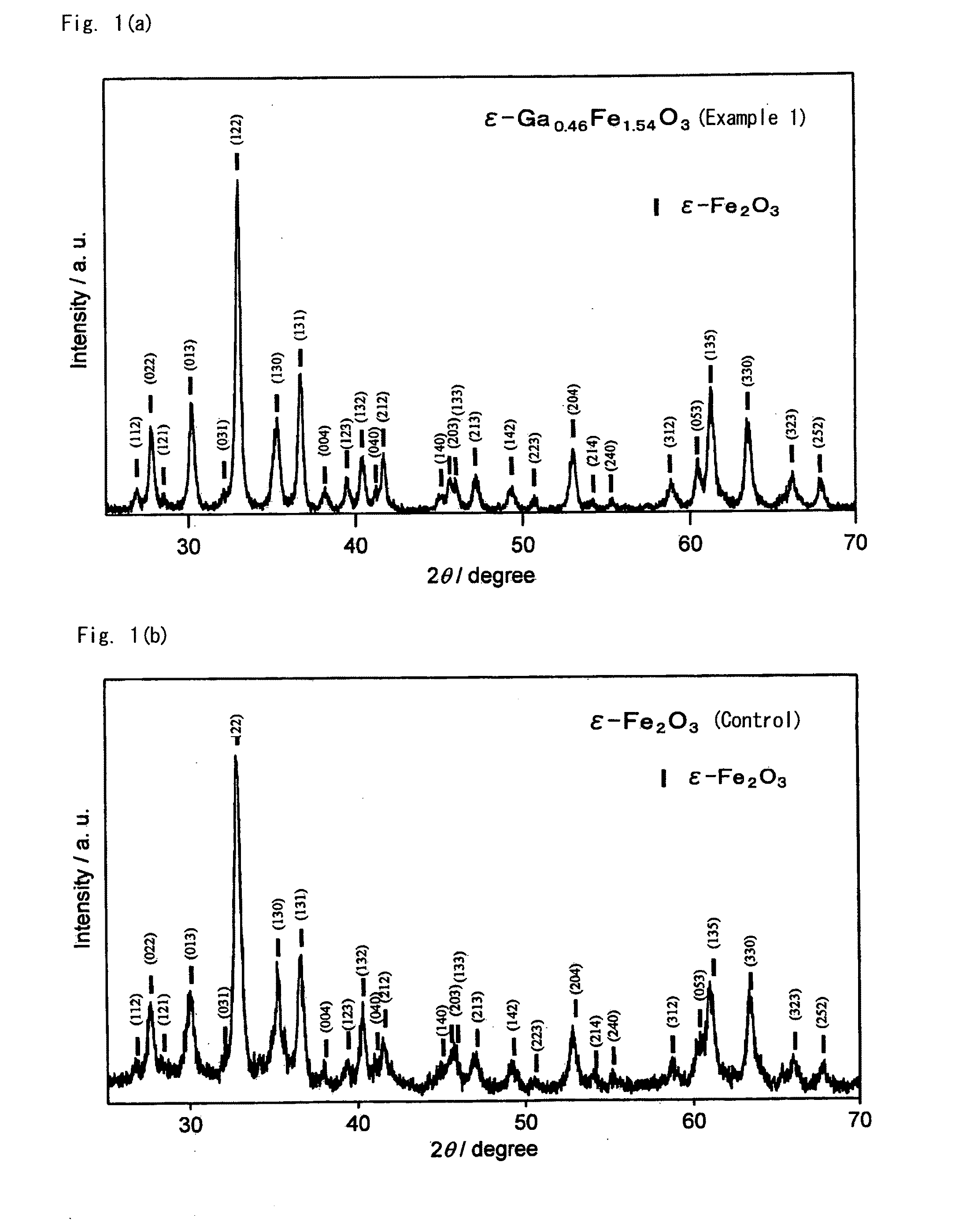
[0063]This Example is to demonstrate production of a crystal having a composition of ε-Ga0.46Fe1.54O3 using Ga as the substituent element M. This is according to the process mentioned below.

[Step 1]

[0064]Two types of micelle solutions, micelle solution I and micelle solution II are prepared.

Preparation of Micelle Solution I:

[0065]6 mL of pure water, 18.3 mL of n-octane and 3.7 mL of 1-butanol are put into a Teflon® flask. 0.002295 mol of iron(III) nitrate 9-hydrate and 0.000705 mol of gallium(III) nitrate n-hydrate are added thereto and dissolved with sufficiently stirring at room temperature. Further, a surfactant cetyltrimethylammonium bromide is added in an amount to give a molar ratio of pure water / surfactant of 30, and dissolved by stirring, thereby giving a micelle solution I. In this, gallium(III) nitrate n-hydrate is a reagent having a purity of 99.9% and n of from 7 to 9, produced by Wako Pure Chemical Industries; and before its use herein, the reagent was quantitatively an...

examples 2 to 6

[0080]Magnetic oxides of Ga-substituted ε-Fe2O3 crystal were produced in the same manner as in Example 1, for which, however, the feeding composition of the micelle solution I in the step 1 was changed as in Table 1; and they were analyzed for the characteristics thereof in the same manner as in Example 1. All these Ga-substituted ε-Fe2O3 crystals gave an X-ray diffraction pattern similar to FIG. 1(a). TEM pictures of these powders are shown in FIG. 3(b) to FIG. 3(f). The electromagnetic wave absorbing characteristics are shown in FIG. 2(a). Table 2 shows, as summarized therein, the analyzed composition and the properties of the magnetic oxides.

examples 7 to 9

[0081]Magnetic oxides of Ga-substituted ε-Fe2O3 crystal were produced in the same manner as in Example 1, for which, however, the feeding composition of the micelle solution I in the step 1 was changed as in Table 1. The obtained Ga-substituted ε-Fe2O3 crystals gave an X-ray diffraction pattern similar to FIG. 1(a). TEM pictures of the obtained particles are shown in FIG. 3(g) to FIG. 3(i).

[0082]The oxide powder was filled in a paper cylinder having a diameter of 40 mm and a height of 10 mm, thereby forming a packed structure, which was analyzed for the electromagnetic wave absorbing characteristics thereof within a range of from 96 to 140 GHz. Using a network analyzer of from 8 GHz to 11.8 GHz and a 12-power upconverter, the above-mentioned high-frequency test was realized. The transmitting and receiving antennas are horn antennas. The results are shown in FIG. 2(b). Table 2 shows the analyzed composition and the characteristics of the magnetic oxides.

TABLE 1Step 1Step 2Step 3Step ...


PUM

PropertyMeasurementUnit
Frequencyaaaaaaaaaa
Frequencyaaaaaaaaaa
Frequencyaaaaaaaaaa

Abstract

Disclosed is a magnetic crystal for electromagnetic wave absorbing materials, having a structure of ε-MxFe2-xO3 with 0<x<1, which has the same space group as that of an ε-Fe2O3 crystal and which is derived from an ε-Fe2O3 crystal by substituting a part of the Fe site therein with M. In this, M is a trivalent element having an effect of lowering the coercive force Hc of ε-Fe2O3 crystal by the substitution. Concretely, the element M includes Al and Ga. An electromagnetic wave absorber having a packed structure of particles having such a substituent element M-added “M-substituted ε-Fe2O3 crystal” as the magnetic phase may control the electromagnetic wave absorption peak frequency depending on the degree of substitution with the element M, and for example, the invention gives an electromagnetic wave absorber applicable to a 76 GHz band for on-vehicle radars.

Description

TECHNICAL FIELD[0001]The present invention relates to a magnetic crystal comprising an ε-Fe2O3-based iron oxide, which is a magnetic crystal suitable for electromagnetic wave absorbers for use in a high-frequency band of 25 GHz or more, as well as to an electromagnetic wave absorbing material and an electromagnetic wave absorber comprising it.PRIOR ART[0002]Recently, with advancement of the information and communication technology, electromagnetic waves in various frequency bands have come to be used in popular applications. For example, there may be mentioned mobile telephones, wireless LAN, satellite broadcasting, intelligent transport systems, nonstop electronic toll collection systems (ETC), advanced cruise-assist highway systems (AHS), etc. With such diversification of electromagnetic wave applications in high-frequency bands, there may occur various problems of trouble, error and malfunction owing to interference between electronic components, and measures for them may be impo...

Claims


Application Information

Patent Timeline
IPC IPC(8): H01Q17/00H01F1/01C04B35/26
CPCB82Y30/00H05K9/0075C01G49/0045C01P2002/72C01P2004/04C01P2004/64C01P2006/42C04B35/26C04B35/62807C04B35/62813C04B35/62823C04B35/62886C04B2235/3217C04B2235/3274C04B2235/3286C04B2235/5454H01F1/344C01G49/0018
Inventor OHKOSHI, SHIN-ICHIKUROKI, SHIROSAKURAI, SHUNSUKENAMAI, ASUKASATO, KIMITAKASASAKI, SHINYA
Owner THE UNIV OF TOKYO
Why Eureka
Try Eureka