Filling machine for highly compressed gas

a filling machine and gas technology, applied in the direction of positive displacement liquid engines, hose connections, piston pumps, etc., can solve the problems of high output gas pressure, inability to meet common requirements, and most devices or machines have a too slow filling speed, so as to reduce rotation speed, avoid or mitigate any possible damage to the operating components, and large torque

Inactive Publication Date: 2010-09-23
POWER TECH DEV
View PDF5 Cites 14 Cited by
  • Summary
  • Abstract
  • Description
  • Claims
  • Application Information

AI Technical Summary

Benefits of technology

[0011]An object of the present invention is to provide a filling machine for highly compressed gas which is a gas compressing machine using a high pressure while not using lubricant, whose function is to fill various highly compressed clean dry gas, such as oxygen, medical oxygen, nitrogen, argon, air, carbon dioxide, into an extra high pressure gas tank; the technical advantage of the present invention also lies in that it allows achievement of a filling pressure which is much higher than that generally provided in the current market, and therefore, the present invention can match and satisfy the need of an extra high pressure gas tank made of composite material available in the current market, which has a large capacity, and at the same time highly increases the speed for filling gas into a high pressure gas tank so that it substantially reduces the time for filling gas into a high pressure gas tank; therefore, by means of the simple and efficient high-compression technology provided by the present invention, common consumers or persons in various specialized fields can easily store and carry a larger volume of gas, which is stored into a high pressure gas tank after being highly compressed, for various applications.
[0012]A filling machine for highly compressed gas provided by the present invention mainly comprises: at least two oscillating type compression gas cylinders which are connected in series by a plurality of one-way valves and hoses so as to constitute a high-compression mechanism; a driving shaft; a plurality of eccentric driving wheels which are fixedly mounted on the driving shaft in sequence spaced apart by a selected angle so as to constitute a eccentric driving mechanism; an electric driver; a mechanical reduction gearbox which is connected to the electric driver; a supporting shaft which is fixedly mounted in a solid upright framework, wherein the driving shaft extending from the reduction gearbox is supported by the two side walls of the framework; the heads of the at least two oscillating type compression gas cylinders is fitted over one supporting shaft; a piston, a piston rod and a slip ring are fixedly joined into an integral block, wherein the slip ring is fitted over the eccentric driving wheel and the eccentric driving wheel is rotatable with respect to the slip ring; when the electric driver is powered, the electric driver rotates and drives the reduction gearbox to reduce the rotation speed according to a reduction ratio and transfer the rotation movement to the driving shaft so that the driving shaft rotates at a low speed and a large torque; when the driving shaft rotates at a low speed, the center of the eccentric driving wheel rotates clockwise along a circular trace, and the movement trace of the center of the eccentric driving wheel is centered on the driving shaft; when the center of the eccentric driving wheel performs a circular movement, the eccentric driving wheel immediately drives the integral block of the slip ring, the piston rod and the piston to reciprocate linearly with respect to the gas cylinder barrel; the electric driver, the reduction gearbox, the eccentric driving wheel and the driving shaft jointly compose an eccentric driving mechanism which operates to drive at least two oscillating type compression gas cylinders to perform a gas compressing operation successively; the cylinder bores of the at least two compression gas cylinders decrease stage by stage in sequence, wherein the cylinder bore of the first stage compression gas cylinder is the largest, the cylinder bore of the second stage compression gas cylinder is relatively smaller and the cylinder bore of the third or higher stage compression gas cylinder is seven smaller in sequence, and the cylinder bore of the highest stage compression gas cylinder is the smallest.
[0013]The high-compression technology of the filling machine for highly compressed gas provided by the present invention has a process as follows:
[0015]The present invention illustrates a filling machine for highly compressed gas in the

Problems solved by technology

In recent years and at present, there are a number of published or announced patent documents which provide similar gas compressing devices based on the technologies of using eccentric driving wheels and using a plurality of compression gas cylinders, or a number of such products which have been sold in the market; however, gas compressing or filling devices or machines provided to common consumers or various specialized fields in the market at present for simple and convenient use still cannot meet common requirements, two defects of which are as follows: firstly, the output gas pressure cannot meet the high requirements at present, and thus they can only fill conventional gas tanks, but generally cannot meet or match the needs of containment of more highly compressed gas in high pressure gas tanks made of composite materials in present advanced science and technology; secondly, even if at present there are similar high pressure gas compressing or filling devices or machines which are able to match the use of high pressure gas tank in the market, most of the devices or machines have a too slow filling speed.

Method used


Image

  • Filling machine for highly compressed gas
  • Filling machine for highly compressed gas
  • Filling machine for highly compressed gas

Examples


Embodiment Construction

[0021]The principle and structure of the present invention will now be explained in detail by means of embodiments with reference to figures; however, the embodiments are only provided for illustration, but not to limit the practical extent of the present invention and the protection scope of its claims.

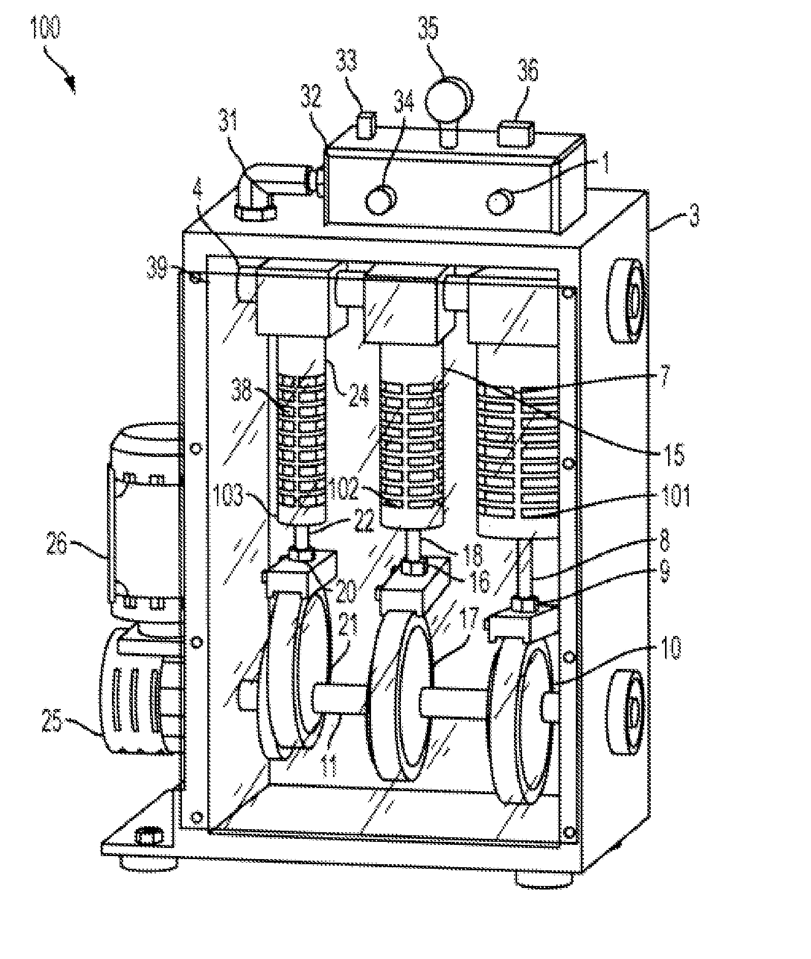
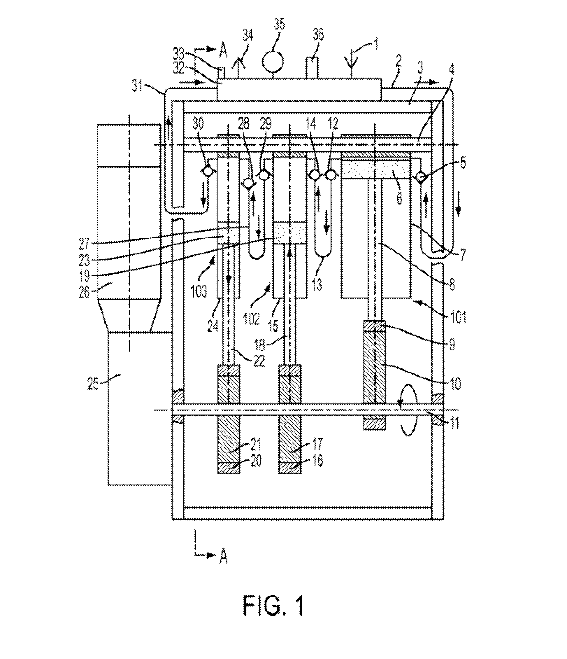
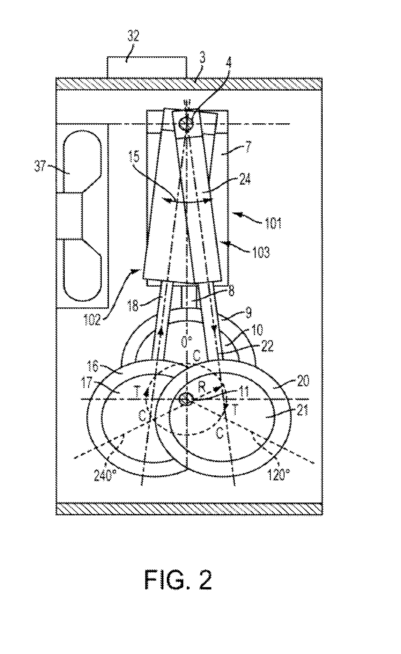
[0022]As shown in FIGS. 1-4, according to a filling machine for highly compressed gas 100 in a preferred embodiment of the present invention, the operation organization of the present invention mainly comprises an eccentric driving mechanism and a set of oscillating type driving mechanisms; the eccentric driving mechanism mainly consists of an electric driver 26, a reduction gearbox 25, a driving shaft 11 and three eccentric driving wheels 10, 17 and 21. According to the preferred embodiment of the present invention, the set of oscillating type driving mechanisms comprises three oscillating type compression gas cylinders 101, 102 and 103, each consisting of a plurality of one-way val...


PUM


Abstract

The present invention refers to a filling machine for highly compressed gas, comprising: an electric driver, a reduction gearbox, a driving shaft, an eccentric driving mechanism, an high-compression mechanism, a cylinder manifold and a framework, wherein the eccentric driving mechanism consisting of at least two eccentric driving wheels is mounted on the driving shaft, the high-compression mechanism consists of at least two oscillating type compression gas cylinders connected in series by a plurality of one-way valves and hoses, and a slip ring, a piston rod and a piston are joined into an integral block wherein the slip ring is fitted over the eccentric driving wheel and the other end of the piston rod is connected to a gas cylinder barrel so as to be fitted over a supporting shaft; the supporting shaft is provided in the framework and the framework is provided with a cylinder manifold on the top thereof, which is provided with a pressure switch, a pressure gauge and a safety valve; the outer circumferential portion of the compression gas cylinder is provided with bump-and-depression textures for heat elimination, the framework is provided with a cooling fan therein, and the framework is provided with a transparent cover; the electric driver drives the reduction gearbox to transfer rotation movement to the driving shaft so as to rotate the eccentric driving wheels, and subsequently drives the integral block of the slip ring, the piston rod and the piston to reciprocate linearly with respect to the gas cylinder barrel in order to compress gas so that the output gas subjected to multistage compression can be filled into a high pressure gas tank.

Description

TECHNICAL FIELD[0001]The present invention mainly relates to a filling machine for highly compressed gas, specialized in highly compression of gas and consequent filling of the gas into a high pressure gas tank, to be used by common consumers or in various specialized fields, so as to match the need of extra high pressure gas tanks present in the current market which are made of composite material and have a large capacity.BACKGROUND ART[0002]The present invention provides a filling machine for highly compressed gas, the compressing operation of which is mainly produced by cooperative operation of a set of high-compression mechanisms and a set of eccentric driving mechanisms; the set of high-compression mechanisms used in the present invention comprises at least two oscillating type compression gas cylinders of different sizes, and the set of the eccentric driving mechanisms comprises at least two eccentric driving wheels which are fixedly mounted on a driving shaft in sequence, spa...

Claims


Application Information

Patent Timeline
IPC IPC(8): F16K21/04F04B35/04F16L35/00F01B29/00F16H53/00
CPCF04B25/00F04B27/0404Y10T74/2101F04B35/04F04B27/0414Y10T137/9247Y10T137/86002
Inventor CHENG, CHEN BONGTAM, PING MAN
Owner POWER TECH DEV
Why Eureka
Try Eureka