
Direct capacitance-to-digital converter

a technology of capacitance and digital converter, applied in the direction of digital-analog converter, capacitance measurement, instruments, etc., can solve the problems of difficult integration into the other existing function blocks operating at low voltage, difficult to overcome the general ic fabrication process, and the powerful digital chips cannot operate with the digital input signal. to achieve the effect of improving the accuracy of the digital signal

Active Publication Date: 2010-09-16
WINDTOP TECH CORP +1
View PDF1 Cites 5 Cited by
  • Summary
  • Abstract
  • Description
  • Claims
  • Application Information

AI Technical Summary

Benefits of technology

"The present invention provides a direct capacitance-to-digital converter that uses a trigger unit to control a plurality of switches and combines with reference voltage to directly measure the change in capacitance and convert into digital signal. This improves the accuracy of the digital signal. The invention also integrates multiple components into a single chip without the need for an external high voltage bias circuit and high quality sensor amplifier. Additionally, the invention uses a differential ADC with a differential integrator to convert the inductive capacitance of the to-be-measured element into a digital signal in a differential manner to improve anti-interference of noise. Overall, the invention solves the drawbacks caused by stray capacitance of the to-be-measured element."

Problems solved by technology

However, these powerful digital chips can only operate with the digital input signal, while most of the electrical signals are analog.
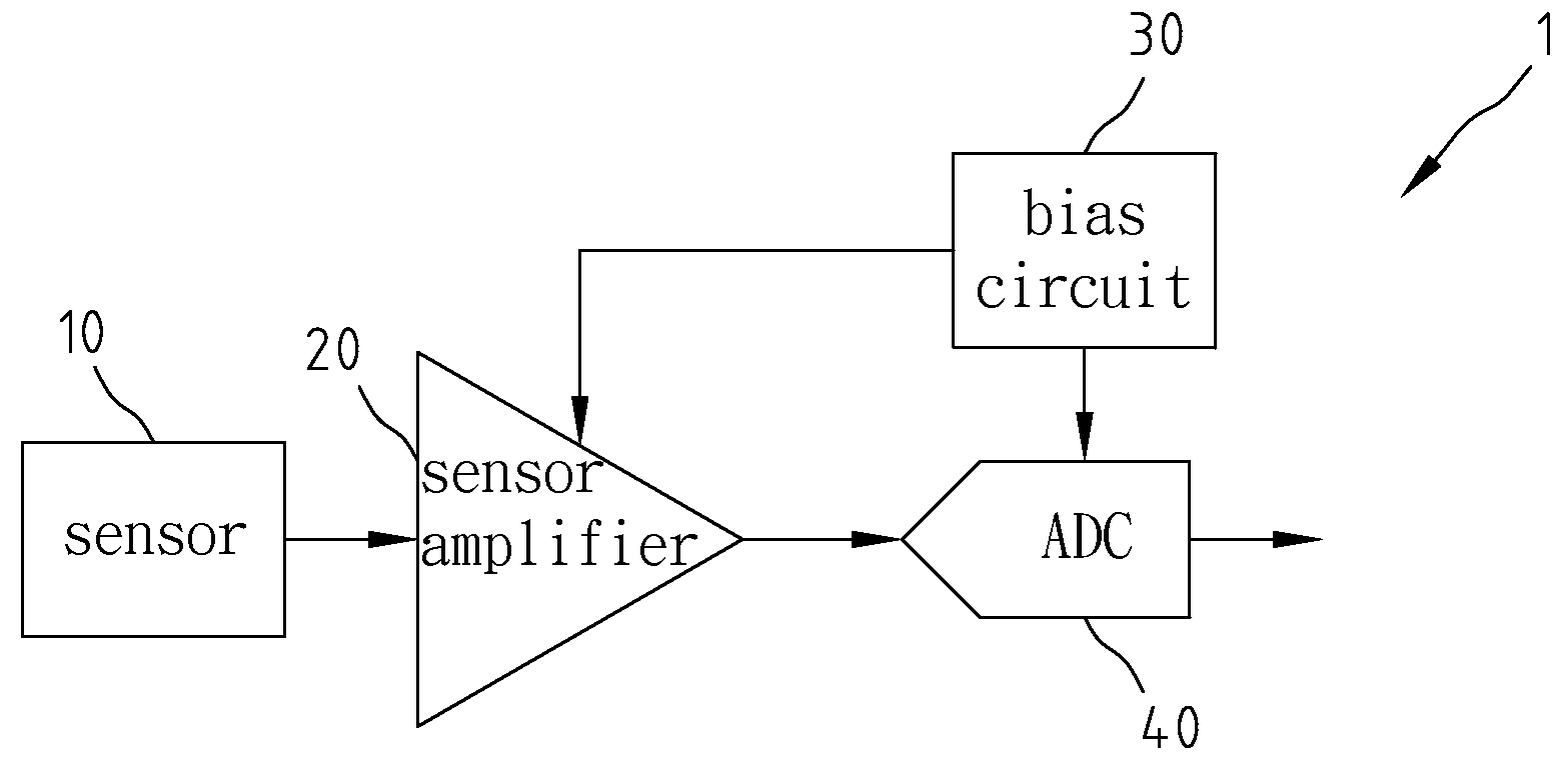
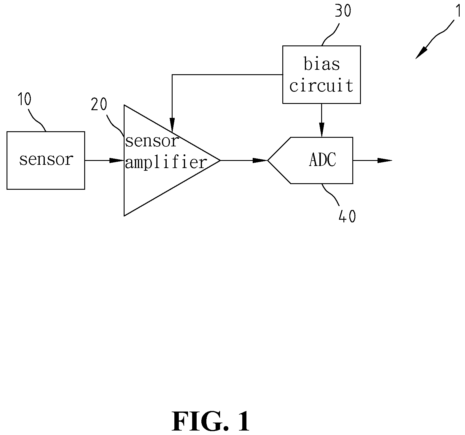
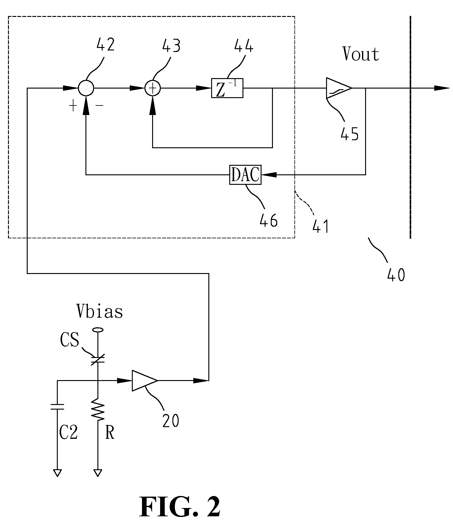
However, the conventional technique has the drawback of requiring a bias circuit able to generate a bias voltage and a first-stage amplifier so as to increase the sensing sensitivity.
However, it is a difficult challenge for the general IC fabrication process to overcome the noise in the bias circuit, and also difficult to integrate into the other existing function blocks operating at low voltage.
Another drawback of the conventional technique is requiring a high quality amplifier to amplify the low inductive voltage to the voltage range processable by ADC.
As the amplifier requires a large size chip area, the chip cost increases and the offset, gain and noise of the amplifier will also increase the signal error.
Yet another drawback of the convention technique is the accuracy of the overall ADC by the stray capacitor due to manufacturing errors or circuit layout, which also varies with the manufacturing process and circuit, leading to the unstable ADC.

Method used


Image

  • Direct capacitance-to-digital converter
  • Direct capacitance-to-digital converter
  • Direct capacitance-to-digital converter

Examples


Embodiment Construction

[0029]FIG. 3 shows a schematic view of the functional block diagram of the direct capacitance-to-digital converter of the present invention. As shown in FIG. 3, a direct capacitance-to-digital converter 2 of the present invention includes an ADC 50 and a trigger unit 60, for sensing the capacitance of to-be-measured capacitor C1, and stray capacitor C2 being the stray capacitance generated by the manufacturing process and being related to capacitor C1, where ADC 50 includes a a first-stage integrator 51, a second-stage integrator 53 and a comparator 55. Trigger unit 60 controls a first end P1 and a second end P2 of to capacitor C1, where stray capacitor C2 is connected to second end P2 of to-be-measured capacitor C1, and trigger unit 60 controls first-stage integrator 51 of ADC 50. Second-stage integrator 53 and comparator 55 can be implemented with general integrator and comparator. It is worth noting that second-stage integrator 53 can be plural serially-connected integrators to i...


PUM


Abstract

A direct capacitance-to-digital converter is provided, including a plurality of switches, an ADC, a reference voltage circuit and a trigger unit. By using trigger unit to control a plurality of switches, and combining the reference voltages outputted by the reference voltage circuit, the converter can directly sense the external to-be-measured capacitor and related stray capacitor, and directly convert the capacitance of the to-be-measured capacitor into accurate digital signal. The present invention can be integrated with other sensors into a single chip to form an integrated direct capacitance-to-digital converter.

Description

FIELD OF THE INVENTION[0001]The present invention generally relates to a direct capacitance-to-digital converter, and more specifically to a converter able to directly sensing the capacitance and converting to precise digital signal without external amplifier.BACKGROUND OF THE INVENTION[0002]With the rapid progress of digital technology and the development of semiconductor manufacturing process, the electronic industry has developed highly integrated and powerful processor or graphic chips. However, these powerful digital chips can only operate with the digital input signal, while most of the electrical signals are analog. Therefore, many analog-to-digital converters (ADC) have been developed to meet different demands, such as, high speed or high resolution ADC. The analog electrical signal is usually generated by sensors, such as, voltage sensor, luminance sensor, temperature sensor, ultrasonic sensor, speed sensor or humidity sensor. In particular, the rapid development of sensors...

Claims


Application Information

Patent Timeline
Patent Type & Authority Applications(United States)
IPC IPC(8): H03M1/12H03M1/66
CPCG01R27/2605H03M3/43H03M3/384
Inventor LU, CHIH-SHIUN
Owner WINDTOP TECH CORP
Learn More