
Operating parameter control of an apparatus for processing data

a technology for controlling the operating parameters of the data processing system, applied in the field of data processing systems, can solve the problems of significant increase in the design and testing complexity of the apparatus, and achieve the effect of reducing the timing margin and avoiding excessive margins

Active Publication Date: 2010-08-26
RGT UNIV OF MICHIGAN +1
View PDF2 Cites 9 Cited by
  • Summary
  • Abstract
  • Description
  • Claims
  • Application Information

AI Technical Summary

Benefits of technology

[0012]The present invention provides a technique whereby signal processing delays are measured over a period of operation such that a large number of instances of an individual signal processing delay are measured. Delay values representing these instances of the signal processing delay being measured are generated. The generated delay values are then analysed to estimate a worse case signal processing delay through the processing stage in which the signal processing delay is measured. One or more operating parameters are then adjusted to provide a timing margin through the processing stage sufficient to satisfy the measured worse case signal processing delay. Measuring over a period of operation of the apparatus enables a statistically reliable estimation of the worse case signal processing delay for the individual apparatus to be found. This in turn permits adjusting of the operating parameters to achieve a reduced timing margin which is nevertheless sufficient to satisfy the real worse case signal processing delay for the individual apparatus concerned. Thus, excessive margins can be avoided and the operating parameters are tuned to the individual apparatus concerned, which will likely be subject to individual process variations and variations dependent upon environmental conditions.
[0013]While it would be appreciated that if the worse case critical path through the processing stage was reliably known in advance, then it might be possible to only measure this known worse case critical path. However, it is more reliable to measure a plurality of different signal paths and generate a plurality of sets of delay values in order to account for individual apparatus variation and other parameters which may influence which signal path is actually the worse case delay signal path for a particular apparatus or at a particular time.
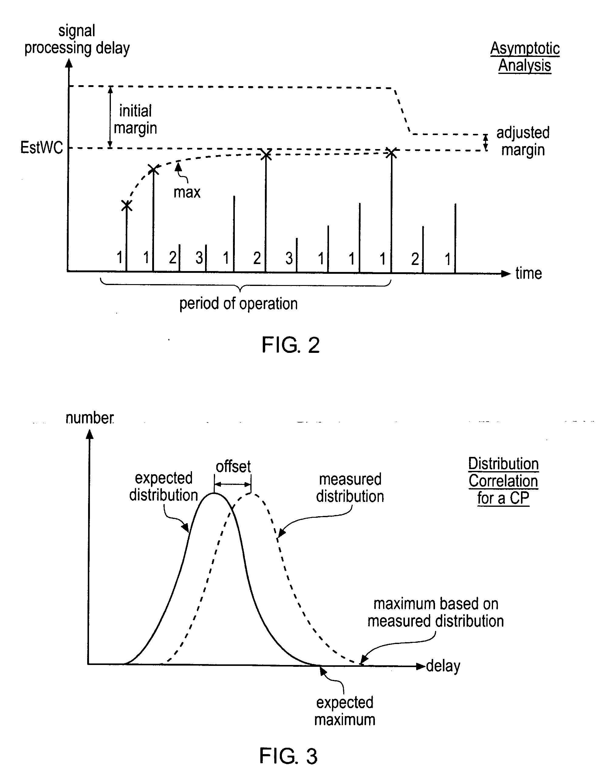
[0016]One analysis technique may be based upon identifying a maximum generated delay value for a signal path being monitored and then identifying when a change in this maximum generated delay value is less than a predetermined amount in a predetermined time interval. The change in the maximum delay value within a given time falling below a threshold value indicates asymptotic behaviour of the generated maximum delay value; this corresponds to a reliable maximum generated delay value that can safely be used to determine appropriate levels of reduced operating parameter margin.
[0028]Efficient embodiments of the present technique may utilise hardware circuits in order to perform at least the steps of measuring and generating. The delay values which are generated may be stored in a memory and given the complexity of the analysis which may be performed this may conveniently be achieved, at least partially, by software which reads the delay values from the memory and then performs the required analysis.

Problems solved by technology

Whilst the above described mechanism for operating parameter control reduces the excessive operating margins normally provided within data processing systems, it suffers from the disadvantage of significantly increasing design and testing complexity of the apparatus.

Method used


Image

  • Operating parameter control of an apparatus for processing data
  • Operating parameter control of an apparatus for processing data
  • Operating parameter control of an apparatus for processing data

Examples


Embodiment Construction

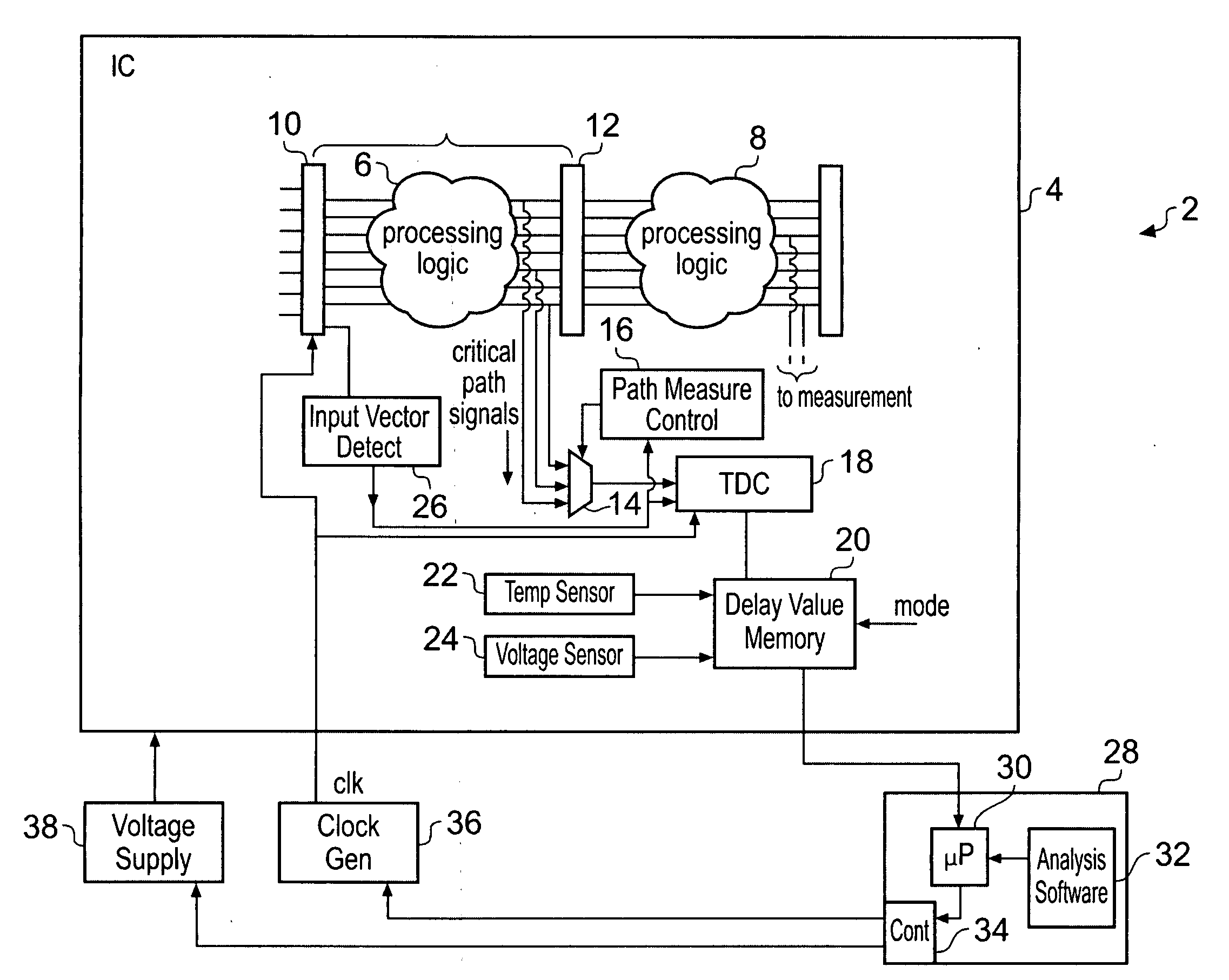
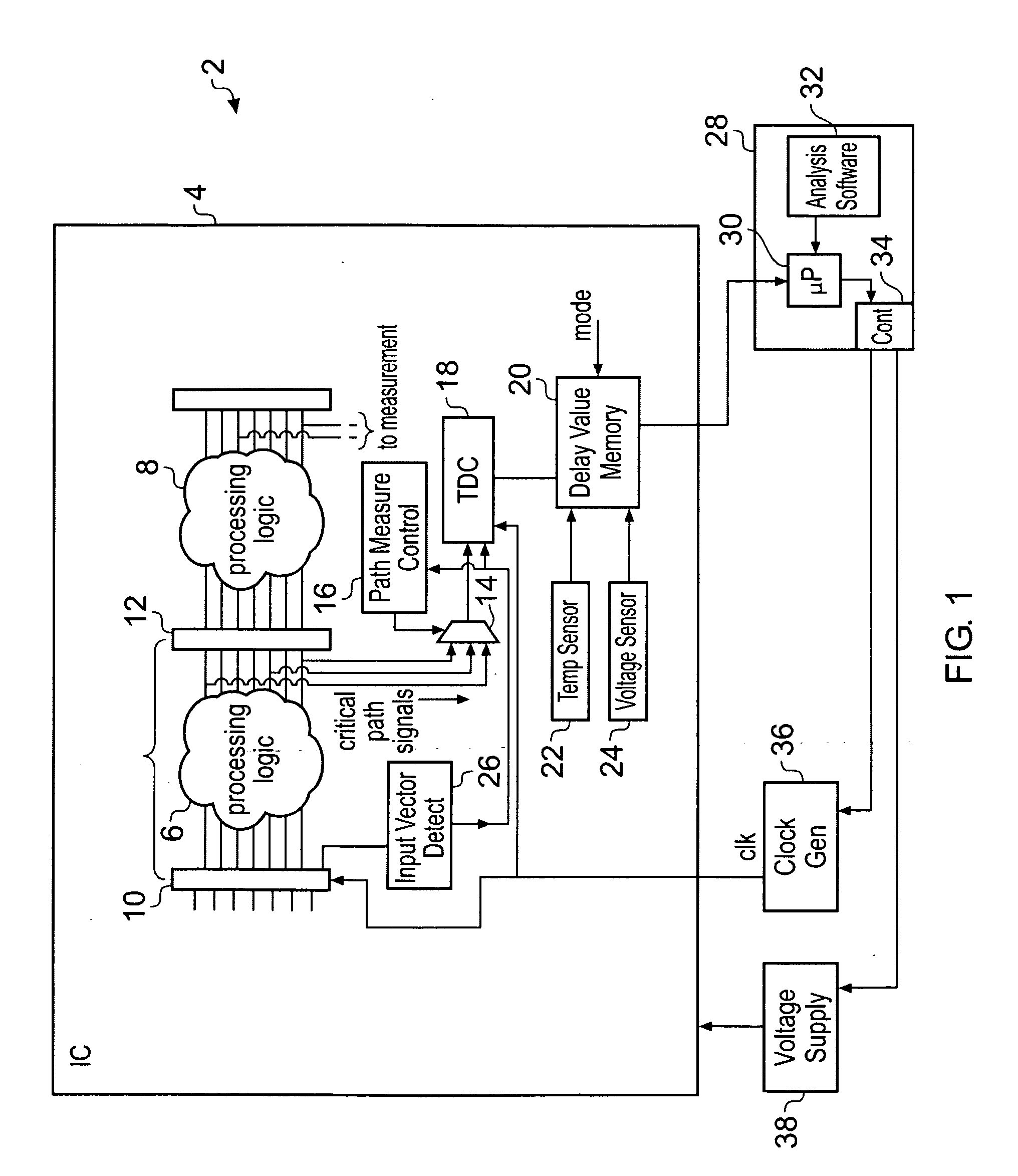
[0048]FIG. 1 schematically illustrates an apparatus for processing data 2 in the form of an integrated circuit 4. This integrated circuit 4 includes a plurality of processing stages. These processing stages comprise processing logic 6, 8 which receives a set of input signal values from registers 10, 12 and generate output signal values to be passed to the next processing stage. The techniques may also be applied to a plurality of processing stages monitored and controlled as if they were a single stage. The segmentation in to stages can be varied and a processing stage need not be restricted to one set of logic between registers. This type of processing logic will be familiar to those in this technical field and is illustrated in stylised form in FIG. 1. An important characteristic of such processing stages is the worst case signal processing delay through the processing stage. This worst case signal processing delay typically controls the operating parameters which may be used, suc...


PUM


Abstract

An apparatus for processing data 2 is provided with a time-to-digital converter 18 which serves to measure signal processing delay through one or more signal paths through a processing stage. This measured delay generates a delay value representing a plurality of instances of the signal processing delay which have been measured. Analysis is performed under software control to estimate a worst case signal processing delay through the processing stage based upon the delay values which have been generated. An adjustment of the operating parameters, such as supply voltage and clock frequency, of the apparatus is made to provide a timing margin through the processing stage sufficient to satisfy the worst case signal processing delay which has been estimated without an excessive margin.

Description

BACKGROUND OF THE INVENTION[0001]1. Field of the Invention[0002]This invention relates to the field of data processing systems. More particularly, this invention relates to the control of operating parameters of data processing systems, such as, for example, control of the operating voltage or operating frequency.[0003]2. Description of the Prior Art[0004]It is known to provide apparatus for processing data which incorporates mechanisms for controlling the operating parameters of that data processing system. As an example, it is known from International Published Patent Application WO-A-2004 / 084072 to provide mechanisms which adjust the operating parameters of a data processing system so as to reduce the operating margins for the purpose of increasing performance and / or efficiency. In the above mentioned example, the operating margins are decreased to the point where a finite non-zero error rate is maintained. When errors occur these are detected and repaired.[0005]Whilst the above ...

Claims


Application Information

Patent Timeline
Patent Type & Authority Applications(United States)
IPC IPC(8): G06F15/00G06F17/18
CPCG05B21/02G06F1/3203Y02B60/1285G06F1/3296Y02B60/1217G06F1/324Y02D10/00
Inventor BLAAUW, DAVID THEODORESYLVESTER, DENNIS MICHAELFICK, DAVID ALANBILES, STUART DAVIDWIECKOWSKI, MICHAEL JOHNHANSON, SCOTT MCLEANCHEN, GREGORY KENGHO
Owner RGT UNIV OF MICHIGAN
Learn More