
Method for filling bottles or similar containers with an oxygen sensitive effervescent liquid beverage filling material under counterpressure and filling machine for the performance of this method

a technology of effervescent liquid beverage and filling material, which is applied in the direction of liquid handling, transportation and packaging, packaging goods types, etc., can solve the problems of inert gas that comprises air or oxygen from the additional duct not being able to enter the headspace of the bowl, and affecting the shelf life and quality of the liquid being bottled

Inactive Publication Date: 2010-08-26
KHS GMBH
View PDF6 Cites 16 Cited by
  • Summary
  • Abstract
  • Description
  • Claims
  • Application Information

AI Technical Summary

Benefits of technology

[0011]An object of the present application is a method and a filling machine which achieves a low consumption of inert gas. In one possible embodiment the inert gas is carbon dioxide gas. The method may provide an economical operation and may avoid, restrict, and / or minimize the absorption of oxygen by the liquid in the bowl with its related disadvantages.SUMMARY
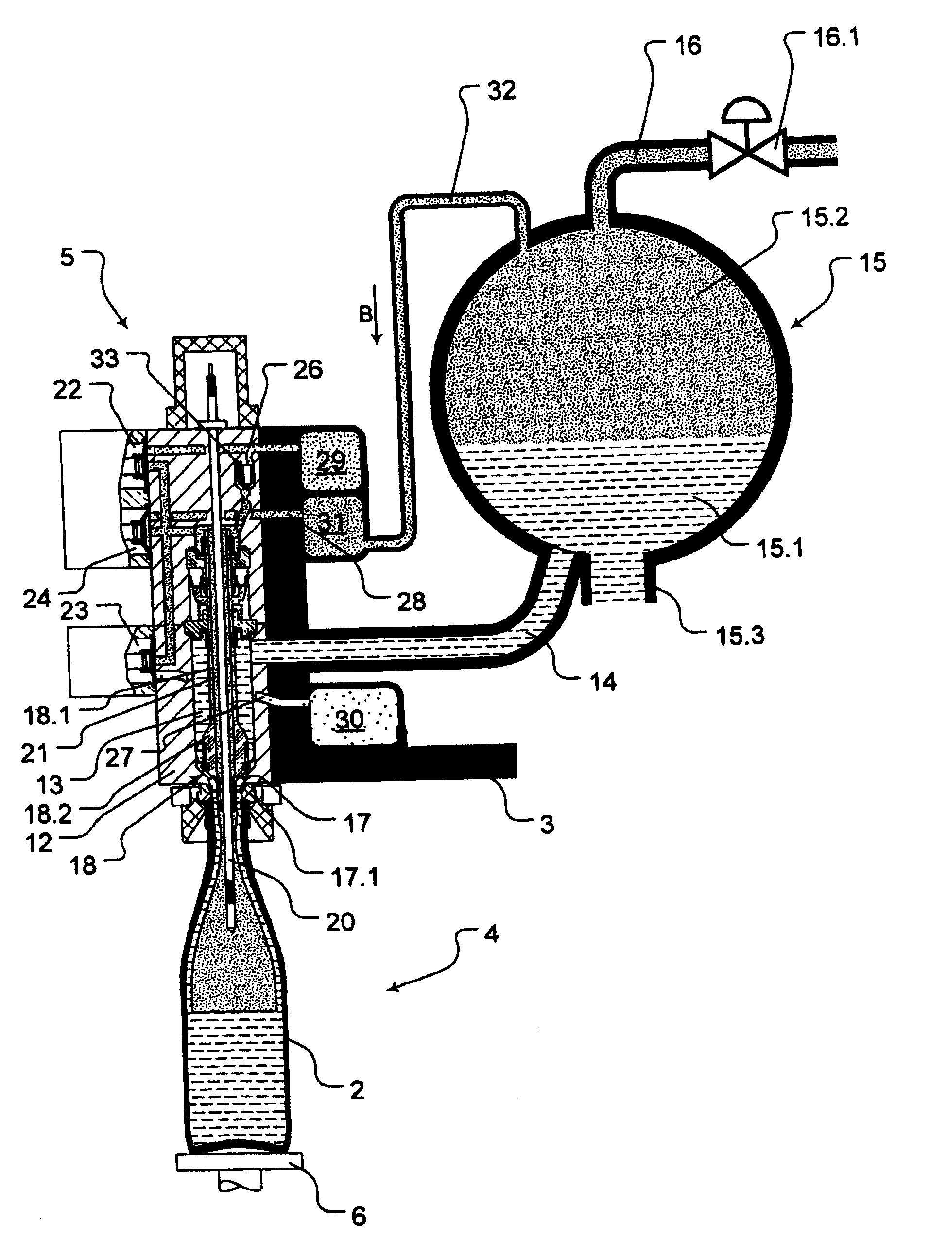
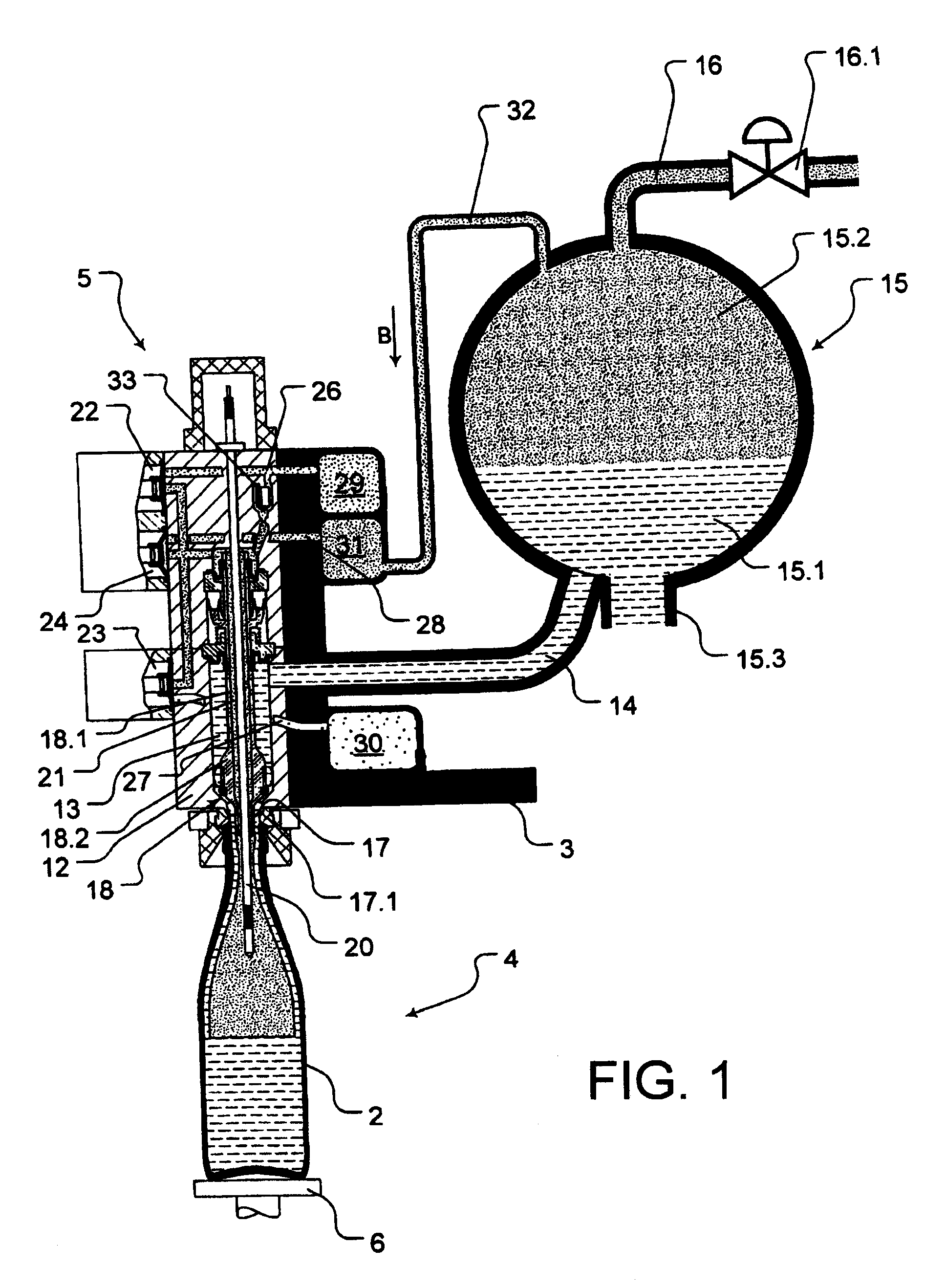
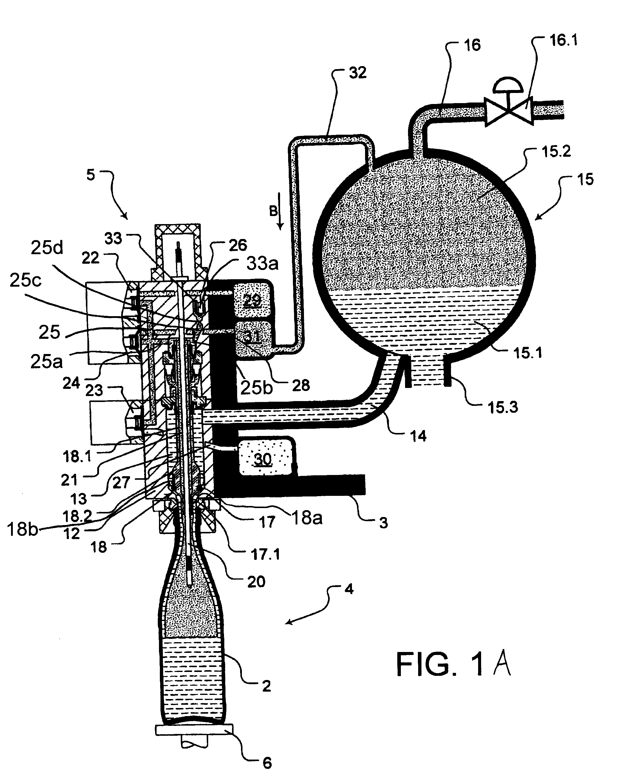
[0012]The present application teaches that this object can be accomplished with a method for filling bottles or similar containers with a liquid under counterpressure, using a filling machine which has, on a rotor a plurality of filling elements, a bowl that is common to the filling elements. The interior of the bowl forms a liquid space which is occupied by the liquid being bottled and a headspace above the liquid for an inert gas under pressure. The filling machine comprises at least one return gas duct which is common to the filling elements or to each of a group of filling elements. Before the filling, the interior of the container is pressurized by means of a controlled gas path of each filling element with inert gas originating from the headspace of the bowl and at the filling pressure. During the filling at least some of the inert gas is displaced from the containers by the incoming liquid into the at least one return gas duct. The individual container is pressurized from at least one additional gas duct that functions as a gas sink and is common to the filling element or a group of filling elements. The additional gas duct is connected by means of at least one gas connection to the headspace of the bowl. This object may also be accomplished with a filling machine with a rotary construction for the filling of bottles or similar containers with a liquid under counterpressure. The filling machine comprises a bowl which is provided on a rotor that can be driven in rotation around a vertical machine axis. The interior of the bowl forms a liquid space which is occupied by the liquid being bottled and a headspace above the surface of the liquid being bottled for an inert gas under pressure (filling pressure). A plurality of filling elements are located on the periphery of the rotor, each of which has a fluid duct which is in communication with the liquid space of the bowl. The filling machine also comprises a discharge opening with a controlled liquid valve, with at least one common return gas duct on the rotor which is common to the filling elements or a group of filling elements, and with controlled gas paths realized in the filling elements, by means of which gas paths the individual container to be filled and located in sealed contact with a filling element can be pressurized with an inert gas at the filling pressure from the headspace of the bowl. This makes possible a removal of the inert gas displaced from the containers during the filling at least partly to the return gas duct. On the rotor for the filling elements or for each group of filling elements, at least one common additional gas duct that functions as a gas sink is provided, which is in communication by means of at least one gas connection with the headspace of the bowl, and with which the filling elements are in communication with their controlled gas paths which effect the pressurization of the containers.

Problems solved by technology

As a result, the liquid being bottled begins to absorb oxygen while it is still in the bowl, and in one possible embodiment at the boundary surface between the liquid being bottled and the inert gas / oxygen mixture above it, which has an adverse effect on the shelf life and quality of the liquid being bottled.
Consequently, inert gas that comprises air or oxygen from the additional duct cannot get into the headspace of the bowl.

Method used


Image

  • Method for filling bottles or similar containers with an oxygen sensitive effervescent liquid beverage filling material under counterpressure and filling machine for the performance of this method
  • Method for filling bottles or similar containers with an oxygen sensitive effervescent liquid beverage filling material under counterpressure and filling machine for the performance of this method
  • Method for filling bottles or similar containers with an oxygen sensitive effervescent liquid beverage filling material under counterpressure and filling machine for the performance of this method

Examples


Embodiment Construction

[0024]In the figures, 1 is a filling machine for the filling of containers realized in the form of bottles 2 with a liquid that houses carbon dioxide such as beer, for example. For this purpose, the filling machine 1 has, and distributed at equal intervals on the periphery of a rotor 3 which is driven in rotation (Arrow A) around a vertical machine axis, a plurality of filling stations 4, each of which comprises a filling element 5, which does not have a filling tube in the illustrated embodiment, and a bottle or container carrier 6 which is located underneath this filling element 5 in the form of a bottle plate that can be raised and lowered in a controlled manner by a lifting device.

[0025]The bottles 2 to be filled are delivered to the filling machine 1 in the upright position in the form of a container stream 2.1 via a conveyor 7, and each container arrives individually via a container inlet 8 at one of the filling positions 4, in which the respective bottle 2 is oriented with it...


PUM

PropertyMeasurementUnit
volumeaaaaaaaaaa
pressureaaaaaaaaaa
saturation pressureaaaaaaaaaa

Abstract

A method for filling bottles or similar containers with an oxygen sensitive effervescent liquid beverage filling material under counterpressure and filling machine for the performance of this method. The abstract of the disclosure is submitted herewith as required by 37 C.F.R. §1.72(b). As stated in 37 C.F.R. §1.72(b): A brief abstract of the technical disclosure in the specification must commence on a separate sheet, preferably following the claims, under the heading “Abstract of the Disclosure.” The purpose of the abstract is to enable the Patent and Trademark Office and the public generally to determine quickly from a cursory inspection the nature and gist of the technical disclosure. The abstract shall not be used for interpreting the scope of the claims. Therefore, any statements made relating to the abstract are not intended to limit the claims in any manner and should not be interpreted as limiting the claims in any manner.

Description

[0001]This application is a Continuation-In-Part application of International Patent Application No. PCT / EP2008 / 000316, filed on Jan. 17, 2008, which claims priority from Federal Republic of Germany Patent Application No. 10 2007 009 435.5, filed on Feb. 23, 2007. International Patent Application No. PCT / EP2008 / 000316 was pending as of the filing date of this application. The United States was an elected state in International Patent Application No. PCT / EP2008 / 000316.BACKGROUND[0002]1. Technical Field[0003]The present application relates to a method for filling bottles or similar containers with an oxygen sensitive effervescent liquid beverage filling material under counterpressure and filling machine for the performance of this method.[0004]2. Background Information[0005]Background information is for informational purposes only and does not necessarily admit that subsequently mentioned information and publications are prior art.[0006]The present application relates to a method for ...

Claims


Application Information

Patent Timeline
Patent Type & Authority Applications(United States)
IPC IPC(8): B65B31/02B65B3/14B65B3/26
CPCB67C3/06B67C3/286B67C3/10
Inventor CLUSSERATH, LUDWIGKRULITSCH, DIETER-RUDOLFHURTEL, MANFRED
Owner KHS GMBH
Learn More