Eureka AIR delivers breakthrough ideas for toughest innovation challenges, trusted by R&D personnel around the world.

Random Body Movement Cancellation for Non-Contact Vital Sign Detection

a non-contact, random body movement technology, applied in the field of non-contact monitoring, can solve the problems of limiting the application of non-contact vital sign sensors, presenting severe interference for accurate detection, and limiting the subject being monitored to remain stationary, so as to achieve accurate measurement results and cancel noise

Active Publication Date: 2010-08-05
UNIV OF FLORIDA RES FOUNDATION INC
View PDF9 Cites 69 Cited by
  • Summary
  • Abstract
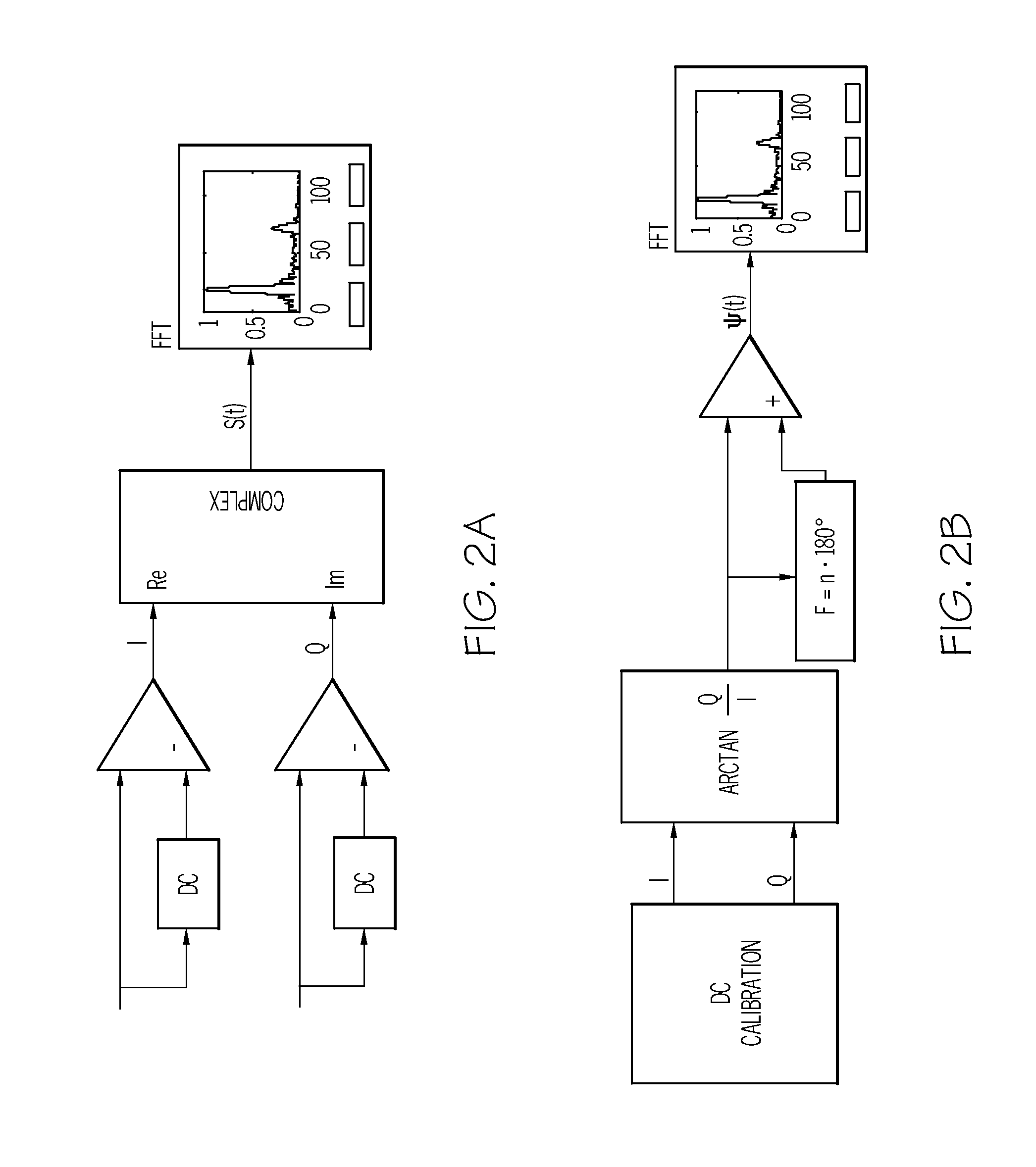
  • Description
  • Claims
  • Application Information

AI Technical Summary

Benefits of technology

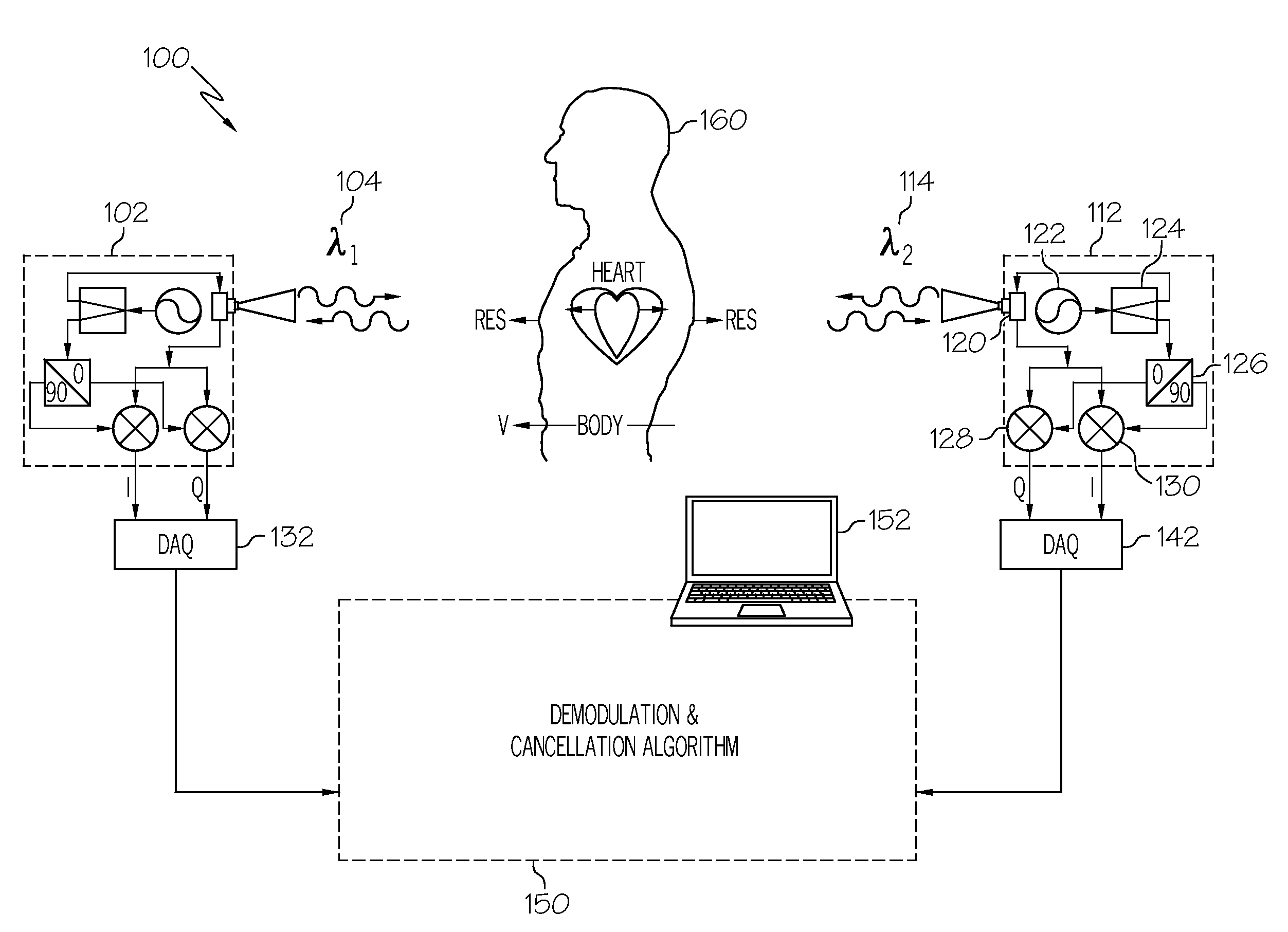
[0007]The present invention provides a method and a system to cancel out noise due to random body movement during non-contact vital sign monitoring. The present invention recovers severely distorted signal to obtain accurate measurement result, solving the main problem prohibiting the wide daily application of non-contact vital sensors.
[0008]Described is a random body movement cancellation in quadrature Doppler radar non-contact vital sign detection using complex signal demodulation and the arctangent demodulation. Applications using the present invention include sleep apnea monitor, lie detector, and baby monitor to eliminate the false alarm caused by random body movement. It has been shown that if the DC offset of the baseband signal is accurately calibrated, both demodulation techniques can be used for random body movement cancellation. While the complex signal demodulation is less likely to be affected by a DC offset, the arctangent demodulation has the advantage of eliminating harmonic and intermodulation interference at high carrier frequencies. In applications where the DC offset cannot be accurately calibrated, the complex signal demodulation is used. Ray-tracing model is used to show the effects of constellation deformation and optimum / null detection ambiguity caused by the phase offset due to finite antenna directivity. Experiments have been performed using 4-7 GHz radar

Problems solved by technology

In practical applications of non-contact vital sign detection, the noise caused by irregular body movement presents severe interference for accurate detection of vital signs such as respiration and heartbeat signal.
Since random body movement is comparable or even stronger than the weak vital sign signal, to some extent it is the main factor limiting the applications of non-contact vital sign sensors.
In many applications such as healthcare, sports, law enforcement, security, it is difficult if not impossible to have the subject being monitored to remain stationary.

Method used


Image

  • Random Body Movement Cancellation for Non-Contact Vital Sign Detection
  • Random Body Movement Cancellation for Non-Contact Vital Sign Detection
  • Random Body Movement Cancellation for Non-Contact Vital Sign Detection

Examples


example i

5.8 GHz Quadrature Radar

[0073]Simulation results are shown in FIG. 5 for detection from the back of the human body. More specifically FIG. 5 is a graph of demodulation for a 5.8 GHz radar illustrating: (a) a signal detected at heart center (Case I) and at body center (Case II); (b) an actual received signal (Case III); (c) an angular information ψ(t) of the received signal; and (d) baseband spectra obtained by the complex signal demodulation and the arctangent demodulation (the DC component is not shown in the baseband spectrum). The residual phase produced in the electronic circuit was assumed to be 00, which means the Q channel was at the optimum detection point while the I channel was at the null detection point according to the single-beam model.

[0074]FIGS. 5(a) and (b) show the signal trajectories in the constellation graph. As predicted in Section II, signals reflected from different parts of the human body are affected by two variations: the phase offset and the radiation int...

example ii

24 GHz Quadrature Radar

[0077]In this example, the carrier frequency was 24 GHz and the residual phase produced in the electronic circuit was assumed to be 450, which means the detection was performed at the middle between the null and the optimum detection points. The constellation plots are shown in FIGS. 6(a) and (b). More specifically, FIG. 6 is a graph of demodulation for a 24 GHz radar illustrating: (a) a signal detected at heart center (Case I) and at body center (Case II); (b) an actual received signal (Case III), with the recovered angular information shown in inset; (c) a baseband spectra obtained by the complex signal demodulation and the arctangent demodulation (DC component not shown in the spectra), according to the present invention. The complex signal demodulation causes harmonic (H2) and intermodulation (Int) interference. Due to fast variation of the phase offset on the surface of the human body, more severe trajectory deformation was observed. However, angular info...


PUM


Abstract

A method and system for cancelling body movement effect for non-contact vital sign detection is described. The method begins with sending on a first electromagnetic wave transceiver a first electromagnetic signal with a first frequency to a first side of a body, such as a person or animal. Simultaneously using a second electromagnetic wave transceiver a second electromagnetic signal is sent with a second frequency to a second side of a body, wherein the first frequency and the second frequency are different frequencies. A first reflected electromagnetic signal reflected back in response to the first electromagnetic wave on the first transceiver is received and a first baseband complex signal is extracted. Likewise a second reflected electromagnetic signal reflected back in response to the second electromagnetic wave on the second transceiver is received and a second baseband complex signal is extracted. The first baseband complex signal is mathematically combined with the second baseband complex signal to cancel out a Doppler frequency drift therebetween to yield a periodic Doppler phase effect.

Description

CROSS REFERENCE TO RELATED APPLICATION [0001]This application is based upon and claims priority from prior U.S. Provisional Patent Application No. 60 / 949,285, filed on Jul. 12, 2007 the entire disclosure of which is herein incorporated by reference.STATEMENT REGARDING FEDERALLY SPONSORED RESEARCH OR DEVELOPMENT[0002]Not Applicable.FIELD OF THE INVENTION[0003]The present invention relates generally to non-contact monitoring and more specifically a method and system to eliminate random body movements during non-contact vital sign monitoring.BACKGROUND OF THE INVENTION[0004]In practical applications of non-contact vital sign detection, the noise caused by irregular body movement presents severe interference for accurate detection of vital signs such as respiration and heartbeat signal. Since random body movement is comparable or even stronger than the weak vital sign signal, to some extent it is the main factor limiting the applications of non-contact vital sign sensors.[0005]To reduce...

Claims


Application Information

Patent Timeline
IPC IPC(8): A61B5/0205
CPCA61B5/05A61B5/0507G06F19/3418G06F17/14A61B5/7214G01S7/032G01S7/354G01S7/40G01S13/34G01S13/536G01S13/87G01S13/88G16H40/67A61B5/0205A61B5/024A61B5/0816A61B5/6823A61B5/7278A61B5/742G16H80/00
Inventor LIN, JENSHANLI, CHANGZHILIU, YA-CHI
Owner UNIV OF FLORIDA RES FOUNDATION INC
Why Eureka
Eureka Blog
Learn More