
In situ formed drain and source regions including a strain-inducing alloy and a graded dopant profile

Active Publication Date: 2010-08-05
ADVANCED MICRO DEVICES INC
View PDF11 Cites 58 Cited by
  • Summary
  • Abstract
  • Description
  • Claims
  • Application Information

AI Technical Summary

Benefits of technology

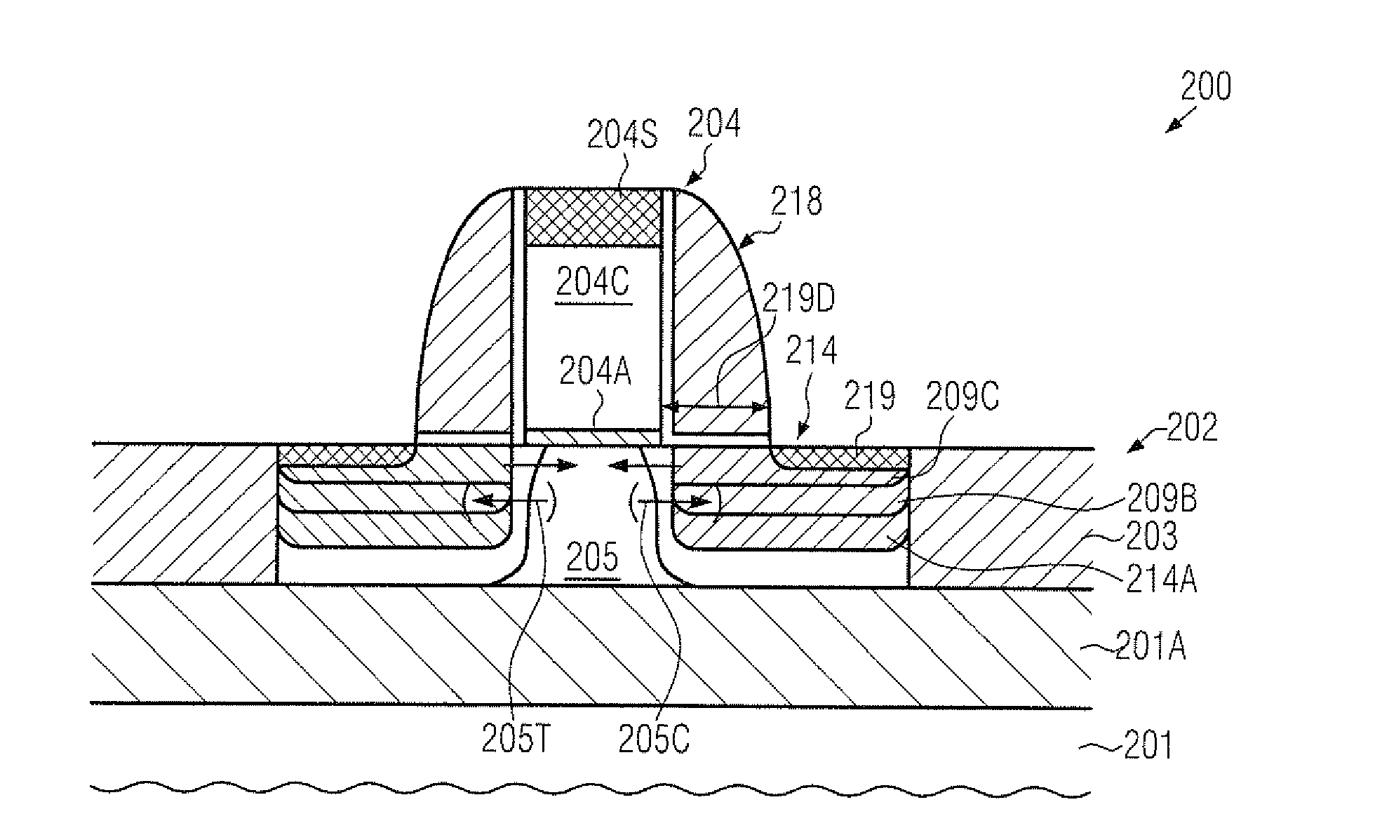
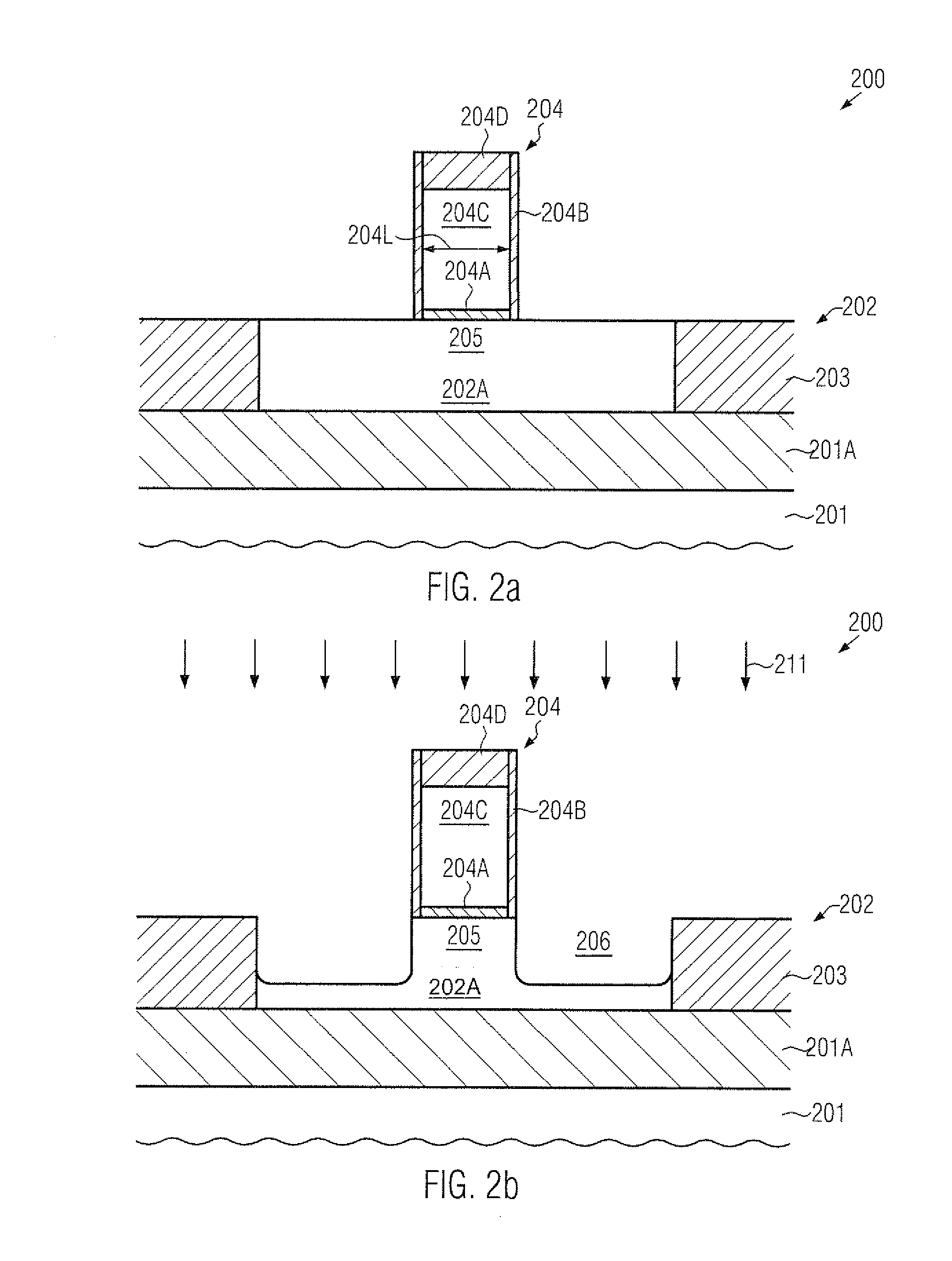
[0016]In general, the present disclosure relates to methods and transistor devices in which complex vertical and lateral dopant profiles may be established in the drain and source regions on the basis of a selective epitaxial growth process for incorporating a strain-inducing semiconductor alloy, which may be provided with a specifically designed in situ dopant concentration, which may result in the desired profile. To this end, the in situ dopant concentration may be provided as a graded dopant profile in which the drain / source dopant species may be provided with a different concentration at different height levels within the epitaxially grown material, wherein a degree of dopant diffusion may thus be determined by the vertical distribution of the dopant species in combination with appropriately selected process parameters for one or more anneal processes, which may generally be performed at a significantly lower temperature compared to conventional strategies. According to other aspects disclosed herein, the in situ doped semiconductor alloy may be advantageously combined with one or more implantation steps, which may be performed prior to the epitaxial growth process so as to avoid implantation-induced damage, while nevertheless providing enhanced flexibility in designing the overall dopant profile. In some illustrative embodiments disclosed herein, the implantation process may be performed through the corresponding cavities, thereby providing enhanced process efficiency, in particular in sophisticated semiconductor devices in which the gate height may not provide sufficient ion blocking capability to allow implantation species to be positioned close to the buried insulating layer of an SOI device. Thus, by incorporating at least a portion of the drain / source dopant species through the cavities, significantly lower implantation energies may be used, thereby avoiding or at least significantly reducing the probability of implanting drain / source dopant species into the channel region through the gate electrode structure.
[0017]Hence, a very efficient manufacturing sequence for providing sophisticated drain and source regions may be accomplished since the number of complex spacer fabrication steps and lithography steps for forming drain and source regions compared to conventional techniques may be reduced.

Problems solved by technology

Hence, the conductivity of the channel region substantially affects the performance of the MOS transistors.
The continuing shrinkage of the transistor dimensions, however, entails a plurality of issues associated therewith that have to be addressed so as to not unduly offset the advantages obtained by steadily decreasing the dimensions of transistors.
However, reducing the dopant concentration in the channel region significantly affects the threshold voltage of the transistor device, thereby presently making a reduction of the dopant concentration a less attractive approach unless other mechanisms are developed so as to adjust a desired threshold voltage.
This, in turn, may further increase stress relaxation in the silicon / germanium alloy due to increased lattice damage and higher dopant diffusion.
On the other hand, however, a lateral distance of the heavily doped silicon / germanium alloy may be required with respect to the channel region since a moderately high dopant gradient may result in a significant dopant diffusion, which may result in a reduced conductivity in the channel region, if increasingly dopant atoms may be incorporated therein.
On the other hand, the reduction of the offset of heavily in situ doped silicon / germanium material may not represent an attractive approach since the significant dopant diffusion may contribute to an overall drain and source dopant profile, which may finally result in increased leakage currents, which may finally lead to total failure of the transistor.

Method used


Image

  • In situ formed drain and source regions including a strain-inducing alloy and a graded dopant profile
  • In situ formed drain and source regions including a strain-inducing alloy and a graded dopant profile
  • In situ formed drain and source regions including a strain-inducing alloy and a graded dopant profile

Examples


Embodiment Construction

[0025]Various illustrative embodiments of the invention are described below. In the interest of clarity, not all features of an actual implementation are described in this specification. It will of course be appreciated that in the development of any such actual embodiment, numerous implementation-specific decisions must be made to achieve the developers' specific goals, such as compliance with system-related and business-related constraints, which will vary from one implementation to another. Moreover, it will be appreciated that such a development effort might be complex and time-consuming, but would nevertheless be a routine undertaking for those of ordinary skill in the art having the benefit of this disclosure.

[0026]The present subject matter will now be described with reference to the attached figures. Various structures, systems and devices are schematically depicted in the drawings for purposes of explanation only and so as to not obscure the present disclosure with details ...


PUM


Abstract

The dopant profile of a transistor may be obtained on the basis of an in situ doped strain-inducing semiconductor alloy wherein a graded dopant concentration may be established along the height direction. Consequently, the semiconductor alloy may be positioned in close proximity to the channel region, thereby enhancing the overall strain-inducing efficiency, while not unduly compromising the finally obtained dopant profile. Furthermore, additional implant species may be incorporated prior to selectively growing the semiconductor alloy, thereby avoiding implantation-induced relaxation of the internal strain.

Description

BACKGROUND OF THE INVENTION[0001]1. Field of the Invention[0002]Generally, the present disclosure relates to integrated circuits, and, more particularly, to transistors having complex dopant profiles and including a strain-inducing alloy, such as a silicon / germanium alloy, for creating strain in the channel region.[0003]2. Description of the Related Art[0004]Integrated circuits comprise a large number of circuit elements on a given chip area according to a specified circuit layout, wherein transistors, such as field effect transistors, represent an important component that is used as switching element, current and / or voltage amplifier. The transistors are formed in and above substantially crystalline semiconductor regions with additional dopant materials that are formed at specified substrate locations to act as “active” regions, that is, to act, at least temporarily, as conductive areas for creating a controlled current flow. Generally, a plurality of process technologies are curre...

Claims


Application Information

Patent Timeline
IPC IPC(8): H01L29/78H01L21/336
CPCH01L29/165H01L29/66507H01L29/6653H01L29/7848H01L29/6659H01L29/66636H01L29/7833H01L29/66537H01L29/0653
Inventor HOENTSCHEL, JANPAPAGEORGIOU, VASSILIOSGRIEBENOW, UWE
Owner ADVANCED MICRO DEVICES INC
Learn More