
Countercurrent tangential chromatography methods, systems, and apparatus

a tangential chromatography and countercurrent technology, applied in the field of chromatography, can solve the problems of inability to make significant improvements in the column chromatography process, and inability to achieve significant improvement. achieve the effect of increasing the efficiency of the system

Active Publication Date: 2010-08-05
CHROMATAN
View PDF1 Cites 13 Cited by
  • Summary
  • Abstract
  • Description
  • Claims
  • Application Information

AI Technical Summary

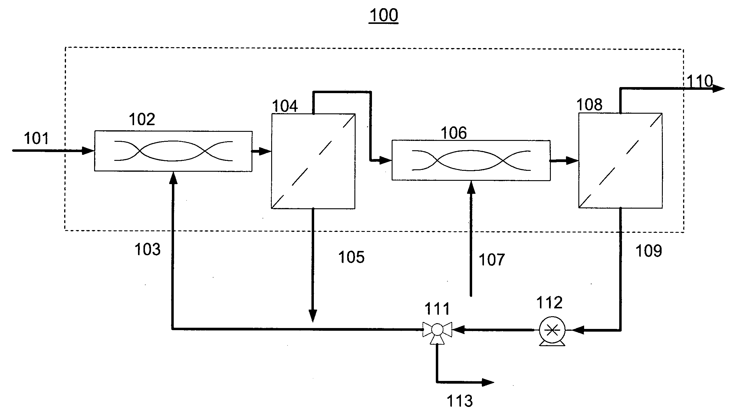
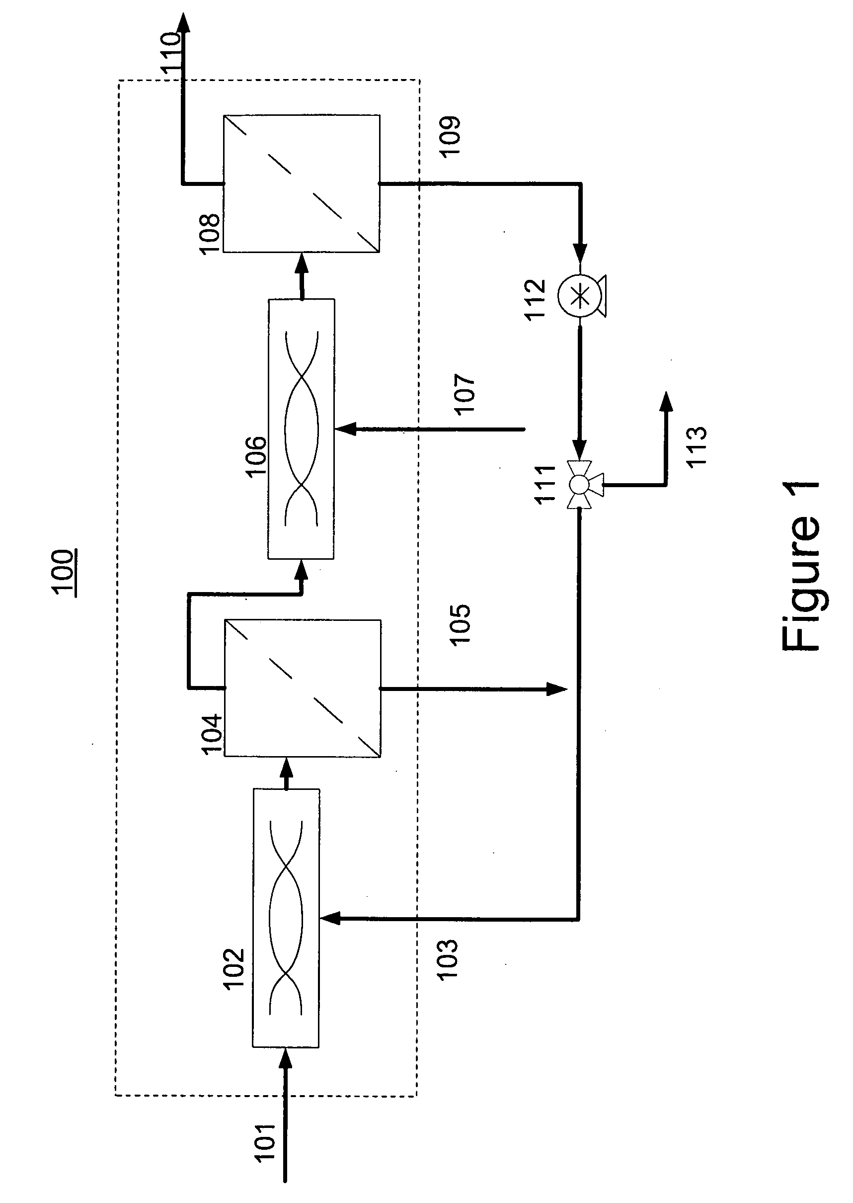
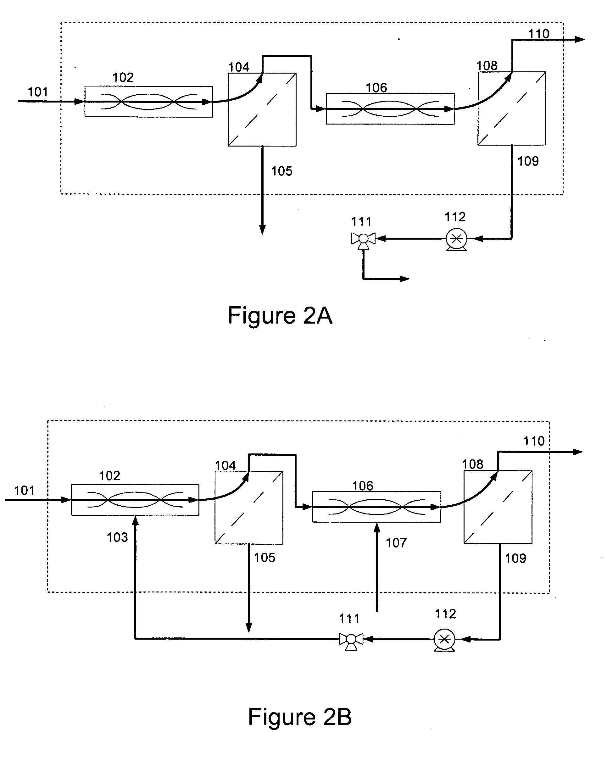
Benefits of technology

[0011]Therefore, one embodiment of the present invention is a scalable, reliable and disposable technology that utilizes a principle of recycling to significantly increase process efficiency, increase the scale of operation, and decrease resin costs.
[0012]In the present invention, the chromatography column is replaced by a module that consists of two or more interconnected tangential flow filters and static mixers. The chromatography resin flows through this module in a single pass, while similar operations to a regular chromatographic process are performed on the resin (binding, washing, elution, regeneration, and equilibration). The buffers for these operations are pumped into the module in a countercurrent direction to the flow of resin, and permeate solutions from later stages are recycled back into previous stages. This creates concentration gradients in the permeate solutions of the tangential flow filters in the countercurrent direction to resin flow, thus saving buffer volume and increasing process efficiency. The permeate solutions from binding, washing, equilibration and regeneration operations are put to waste. The permeate solution from the elution operation is the purified product stream which is collected in a separate product tank.
[0023]Another embodiment of the present invention is the system described above further comprising an additional countercurrent tangential chromatography stage comprising a third mixer (530) and a third filter (532), for increasing efficiency of the system. (See FIG. 5.)

Problems solved by technology

First, no significant improvements have been made to the column chromatography process in the past 30 years—most of the work in the industry has been focused on new resin development. A notable exception is membrane chromatography which was recently adopted by the industry.
Second, upstream technology has improved tremendously in the same time period—the bioreactors are larger (up to 20,000 liters), and the titers are much higher (up to 15 g / L compared with 1-2 g / L five years ago). As a result of longer fermentation times, there are generally more impurities in the bioreactor effluent solution. All of the above reasons result in a much heavier load for the downstream purification.
Third, column chromatography has inherent physical limitations. Columns larger than 2 meter in diameter do not scale up. The largest columns in the market are 2 meter diameter and 40 cm bed height. They fit 1,250 L of resin. Assuming a binding capacity of 30 g / L of resin (common Protein A resin capacity for monoclonal antibodies), a single cycle can bind 38 kg. A 20,000 L bioreactor with an output of 10 g / L would produce a load of 200 kg. This means that the biggest column in the market would have to run at least 6 full cycles to process a single batch. The operation can take up to 24 hrs and can result in a significant bottleneck for the manufacturing process.
The column chromatography technology because of its inherent limitation cannot be a part of the disposable trend.
Therefore, it is currently impossible to have a completely disposable downstream process—a purification train must include a chromatography step which cannot be disposable.

Method used


Image

  • Countercurrent tangential chromatography methods, systems, and apparatus
  • Countercurrent tangential chromatography methods, systems, and apparatus
  • Countercurrent tangential chromatography methods, systems, and apparatus

Examples


Embodiment Construction

[0035]Definitions: The following terms of art shall have the below ascribed meanings throughout this Specification.

[0036]Binding mode is a stage of operation during which resin and unpurified product form a reversible complex.

[0037]Washing mode is a stage of operation during which resin with bound product is washed with a washing buffer to rid the resin of impurities.

[0038]Elution mode is a stage of operation during which the complex of resin and the product is reversed and the purified product is collected.

[0039]Regeneration mode is a stage of operation during which the resin is cleaned for the purpose of reuse or for later cycles.

[0040]Equilibration mode is a stage of operation during which the system is equilibrated in a neutral buffer.

[0041]As stated in the Summary of the Invention section, in the present invention, the chromatography column is replaced by a module that consists of two or more interconnected tangential flow filters and static mixers. The chromatography resin flo...


PUM


Abstract

This invention relates to a breakthrough in the art of chromatography allowing 1) larger scale of operation; 2) faster processing time; 3) disposability; 4) reduction of media / resin expenses; and 5) a reduction of capital equipment investment. In this invention, the chromatography column is replaced by a module that consists of two or more interconnected tangential flow filters and static mixers. The chromatography resin flows through this module in a single pass, while similar operations to a regular chromatographic process are performed on the resin (binding, washing, elution, regeneration, and equilibration). The buffers for these operations are pumped into the module in a countercurrent direction to the flow of resin, and permeate solutions from later stages are recycled back into previous stages. This creates concentration gradients in the permeate solutions of the tangential flow filters in the countercurrent direction to resin flow, thus saving buffer volume and increasing process efficiency.

Description

REFERENCE TO RELATED APPLICATIONS[0001]This applications claims priority from provisional application U.S. Ser. No. 61 / 150,240, filed on Feb. 5, 2009, and entitled “Counter Current Tangential Chromatography,” the entirety of which is hereby incorporated by reference herein.FIELD OF THE INVENTION[0002]The present invention is generally related to chromatography. More specifically, this invention relates to a method, system, and apparatus of tangential chromatography using countercurrent flow to facilitate separation of the desired product and enhance efficiency of the entire chromatography process.BACKGROUND OF THE INVENTION[0003]There has been a significant and sustained growth in new drug production featuring monoclonal antibodies and other proteins, approximately 15-20% annually. This growth is due to expanding drug pipelines, as well as more efficient cell lines and bioreactor growth optimizations. The annual bio-production costs are currently estimated at $2.6 billion. One of th...

Claims


Application Information

Patent Timeline
Patent Type & Authority Applications(United States)
IPC IPC(8): B01D15/18
CPCG01N30/42B01D15/1807
Inventor SHINKAZH, OLEG
Owner CHROMATAN
Learn More