
Electric car with maximized solar assist

a solar energy and assistive technology, applied in the direction of light-to-electric conversion, transportation and packaging, propulsion parts, etc., can solve the problems of limited speed or driving range, lack of solution to the problem of carrying multiple passengers, and easy to get,

Inactive Publication Date: 2010-08-05
FREEMAN BENJAMIN
View PDF12 Cites 44 Cited by
  • Summary
  • Abstract
  • Description
  • Claims
  • Application Information

AI Technical Summary

Benefits of technology

[0020]The present invention is an extended range solar powered car for eliminating the emission of green house gasses and therefore reducing the threat of global warming.
[0023]The preferred embodiment also provides for three or more wheels, normally four. The wheels support the car from the driving surface, allow the car to move with reduced rolling resistance and in most cases provide a means for transmitting the propulsion force that moves the car forward or in reverse.
[0025]In this prime embodiment, there will also be regenerative braking which creates energy as it slows the car down. To maximize safety, however, regular braking will also be provided.
[0028]While the first variant will be safer in terms of a side impact collision, it will be less stable and more prone to tipping than the second variant in cases of high cross winds while the car is being driven. However, the first variant will be easier to use and maintain since constant opening and closing of the segmented solar roof while the car is parked will probably create maintainence problems. Although the second variant might cost more due to the cost of segmenting the solar roof and being able to open and close the segments as desired, it will look more like a regular car when driven and, therefore, will probably be seen as more stylish and traditional. Part of the reason that the second variant could look more like a regular car is that there is less necessity to make the box where the riders are seated as thin. For instance, the second variant could be built as a fifty five inch wide vehicle and achieve the result of having twice as wide of a solar panel roof when parked by spreading the solar panels to a hundred and ten inches. While doing that might create complications in finding an appropriate parking spot to spread the roof, one could (partly) solve that problem by having the entire roof mechanism move upward to a height above other nearby vehicles. By comparison, the fixed (but tiltable) roof of the first variant could not be wider than a car lane and, therefore, making the inner box half as wide would lead to a maximum width of about forty inches.
[0031]The claims section of this patent mentions that the batteries will be placed for easy removal. In either variant of the prime embodiment, this will be done by setting the batteries on a tray placed in the very back of the vehicle which is set on the car body in such a way that the type of tynes used in forklifts can remove the entire tray with the batteries still affixed to the tray. The primary point of doing this is to allow for a discharged energy storage (or battery) array to be replaced quickly with a fully charged one affixed to an identical tray. This would allow the driver to continue on their way in the same way that a driver can fill his tank with gas and continue on his way. Obviously, the electric connection between the batteries and the remainder of the car must be set up so that a non-electrician can easily disconnect them when a discharged battery array is being removed and then reconnect the newly installed fully charged battery array to the car's electrical system.
[0034]We believe that the combination of features included increases the range of the car without creating a car whose weight, cost or difficulty of using and repairing creates more total disadvantage than a gas driven car. Although the controls, recharging and other features make it slightly more difficult to use, the lowered amount of parts and repair costs (electric cars have far less parts than cars with internal combustion engines) will compensate. In the end, the maintainence and other difficulties associated with owning an all electric version of our car will usually be less than the maintainence and other difficulties associated with owning a normal gas driven car. Especially if one assumes that a network of battery changing stations will eventually be built as many are already planning for, these features convert an electric car from a specialty vehicle for those who only drive short distances or who are willing to spend large sums of money for purely moral purposes into practical cost effective vehicles.

Problems solved by technology

However, it lacks solution to the problems of carrying multiple passengers, ease of getting into and out of the passenger compartment or extended driving range at night or during compromised sun exposure.
However, this approach to reducing green house gasses does little to reduce wind drag and has a very limited speed or driving range if solar power alone is utilized.
However, the disclosure of inventor Treat lacks a solution to the problems of reducing wind drag, and an extended range of travel.
However, the disclosure of inventor Shaffer et al. lacks a solution to the problems of wind drag, driving range during periods of limited sunlight or extended trip driving range.
Such a large vehicle would not be able to use a lower horsepower and lower amp draw motor because it would weigh so much.
Furthermore, it would never fit in a standard parking space.
Most importantly, his patent never made the additional suggestion to use the extra space along the sides of a thin vehicle for solar panel overhangs.
Not only is to too high tech and complex to be produced at a reasonable price, but the mechanism required takes an enormous amount of space.
Hence, building cars designed to accommodate this battery exchanging system is a dead end because the battery exchanging stations will have to charge so much that consumers would find it less expensive to buy and use a car with an internal combustion engine.
While there is related art which has features similar to many of my individual features, there is no related art which singly or in combination fulfills the underlying requirements of creating an affordable electric car that can fulfill the driving requirements of an average driver nearly as well as a car with an internal combustion engine.
Since none of these individuals or groups has come up with any other method for creating an affordable electric car that can fulfill the driving needs of an average driver, it must not be obvious to a person with a reasonable appreciation of the art how this could be done.

Method used


Image

  • Electric car with maximized solar assist
  • Electric car with maximized solar assist
  • Electric car with maximized solar assist

Examples


Embodiment Construction

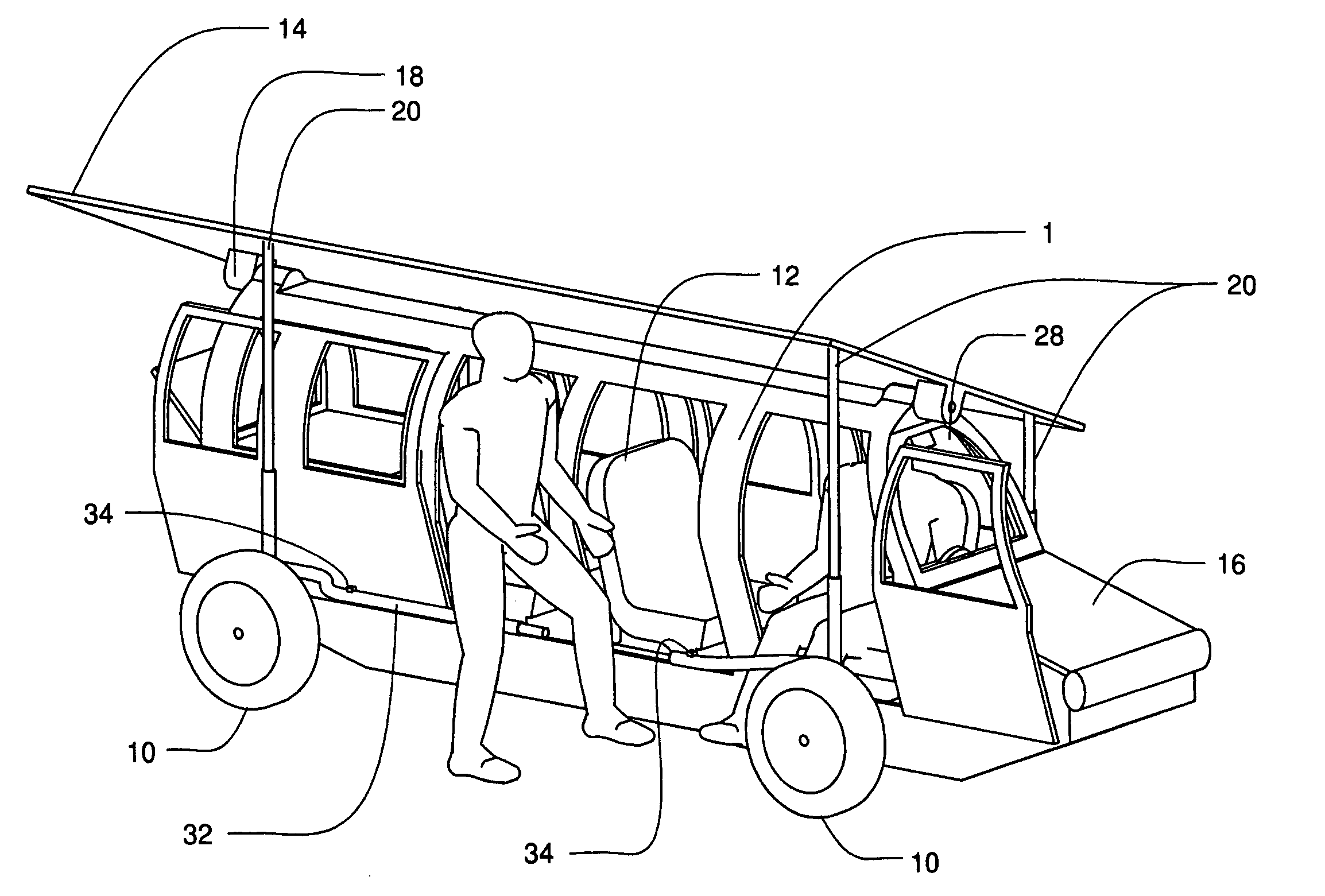
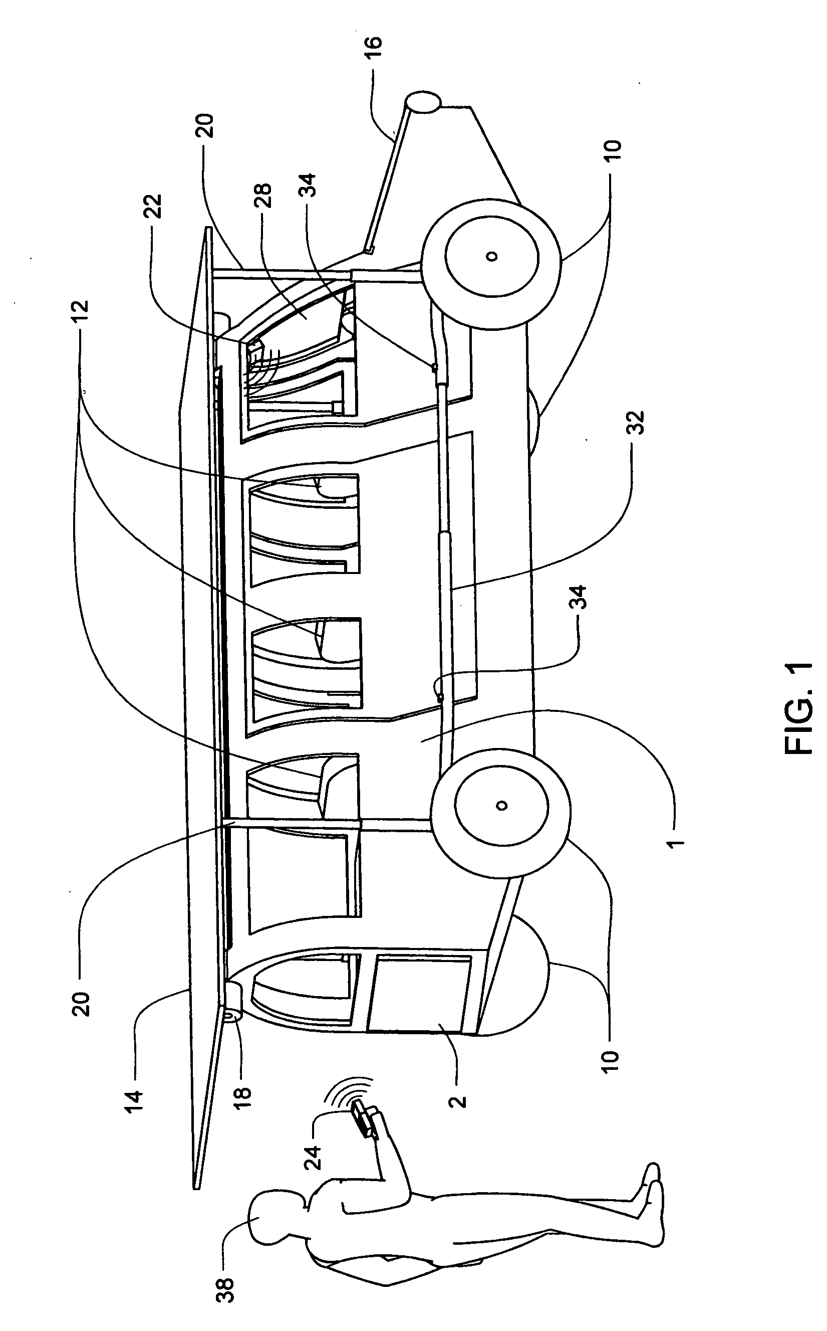
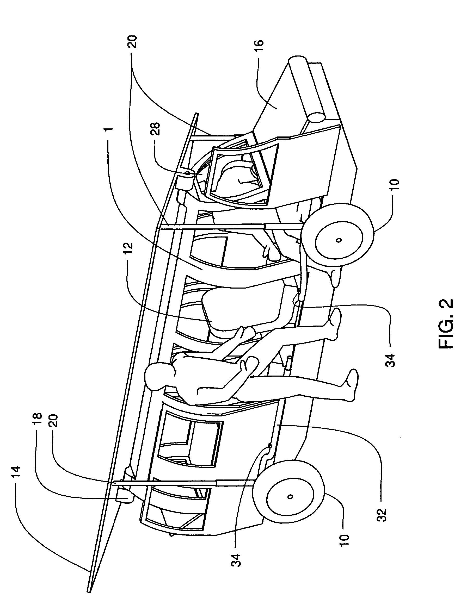
[0075]Referring to FIGS. 1 and 2, the body 1 is supported by the four wheels 10. Located where a hood would normally go on body 1 is the hood solar panel 16. Located on the roof of the body 1 is the solar panel roof 14. Located near the front of the body 1 on the inside near the top of where the windshield 28 is located are the sensor displays 22. Figure one only depicts how the sensor displays 22 can be wirelessly accessed by the communicator 24 that the driver 38 is holding. Between the wheels are side bumpers 32. Mounted on the side bumpers are sensors 34 to tell if the vehicle has suffered a side impact collision 34 which could set off outside air bags. Coming up from the side bumpers 32 are supports 20 which connect with and help support the solar panel roof 14. As you can see by comparing the length of these supports 20 in the figures one and two, these supports 20 can move up and down as the solar panel roof 14 moves up and down. Under the solar panel roof 14 near the back of...


PUM


Abstract

The present invention is an electric car with a maximized solar panel assist. Since batteries are normally charged at night while solar energy is created during the day, this system creates an almost continuous flow of electricity to the batteries. Since the weight and cost of the batteries are the main handicap for electric cars and a continuous flow of electricity minimizes the need for a large and expensive battery system, this is the most logical way to build a viable electric car.

Description

STATEMENT REGARDING FEDERALLY SPONSORED RESEARCH OR DEVELOPMENT[0001]Not ApplicableTHE NAMES OF THE PARTIES TO A JOINT RESEARCH AGREEMENT[0002]Not ApplicableINCORPORATION-BY-REFERENCE OF MATERIAL SUBMITTED ON A COMPACT DISC[0003]Not ApplicableSEQUENCE LISTING[0004]Not ApplicableBACKGROUND OF THE INVENTION[0005]1. Field of the Invention[0006]Because of the expense, political and ecological problems involved with importing oil, the US, and the world, needs electric cars. In fact, the only fundamental impediment to electric cars becoming more important than those with internal combustion engines is the difficulty of building a reasonably priced electric car (or a reasonably priced gas / electric hybrid with the electric motor being the dominant one) that has the range people want. It is also worth noting, however, that a “plug in” pure electric car or a hybrid whose dominant electric motor only relies on plug in electricity and electricity indirectly generated by the internal combustion ...

Claims


Application Information

Patent Timeline
IPC IPC(8): B60K16/00B60L8/00
CPCB60K16/00B60K2016/003B60L8/003Y02T10/90Y02T10/7083Y02T10/7072
Inventor FREEMAN, BENJAMIN
Owner FREEMAN BENJAMIN
Learn More