Ear thermometer and measuring apparatus used with it

a technology of ear thermometer and measuring apparatus, which is applied in the direction of optical radiation measurement, instruments, spectrophotometry/monochromators, etc., can solve the problems of difficult to keep the accuracy of the thermistor for a wide range of ambient temperatures, temperature difference occurs to prevent a correct measurement, and the output of the probe is temporarily destabilized, etc., to achieve easy mass production and easy installation

Active Publication Date: 2010-07-22
BIO ECHO NET
View PDF11 Cites 6 Cited by
  • Summary
  • Abstract
  • Description
  • Claims
  • Application Information

AI Technical Summary

Benefits of technology

[0021]An object of the present invention is to provide an ear thermometer that is based on the ear thermometer of Patent Document 2

Problems solved by technology

If an external factor applies a sudden temperature change, a head of the package and the heat sink of the thermopile produce a temperature difference to transiently destabilize the output of the probe.
If thermal bonding between the thermopile cold junction and the thermistor is bad, a temperature difference occurs to prevent a correct measurement.
Even thermistors based on the same standard have different B-constants (the B-constant representing the magnitude of a resistance change obtained from temperatures at optional two points on a resistance-temperature characteristic curve), and therefore, it is difficult for the thermistor to keep accuracy for a wide range of ambient temperatures.
The ear thermometer according to Patent Document 1, however, has problems of hardly being miniaturized, consuming large power, involving a complicated circuit, and partly needing expensive parts to increase a total cost.
The ear thermometer according to Patent Document 1 is appropriate for once measuring a body temperature in a short period of time, bu

Method used


Image

  • Ear thermometer and measuring apparatus used with it
  • Ear thermometer and measuring apparatus used with it
  • Ear thermometer and measuring apparatus used with it

Examples


Embodiment Construction

[0055]Embodiments of the present invention will be explained in detail with reference to the drawings.

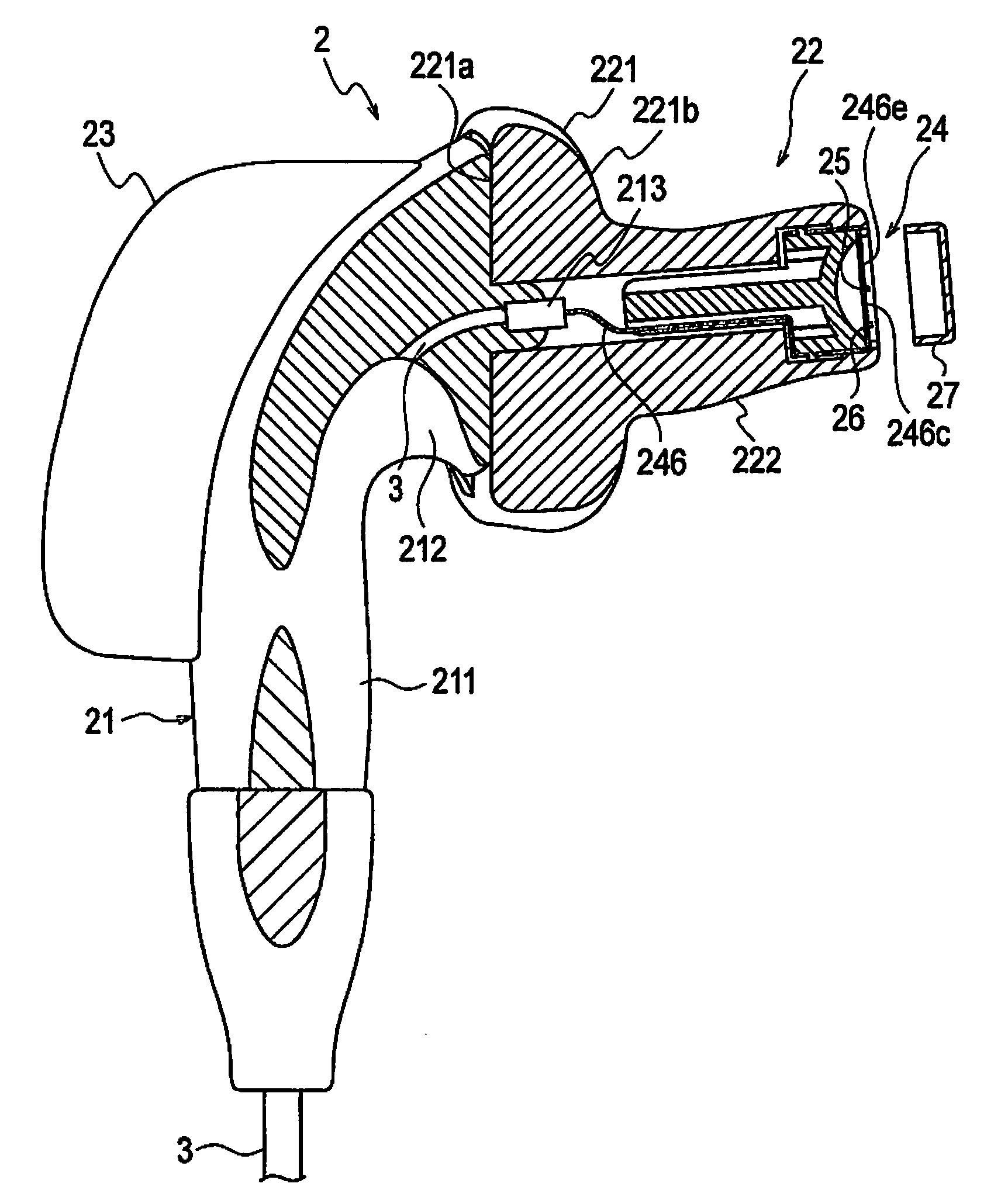
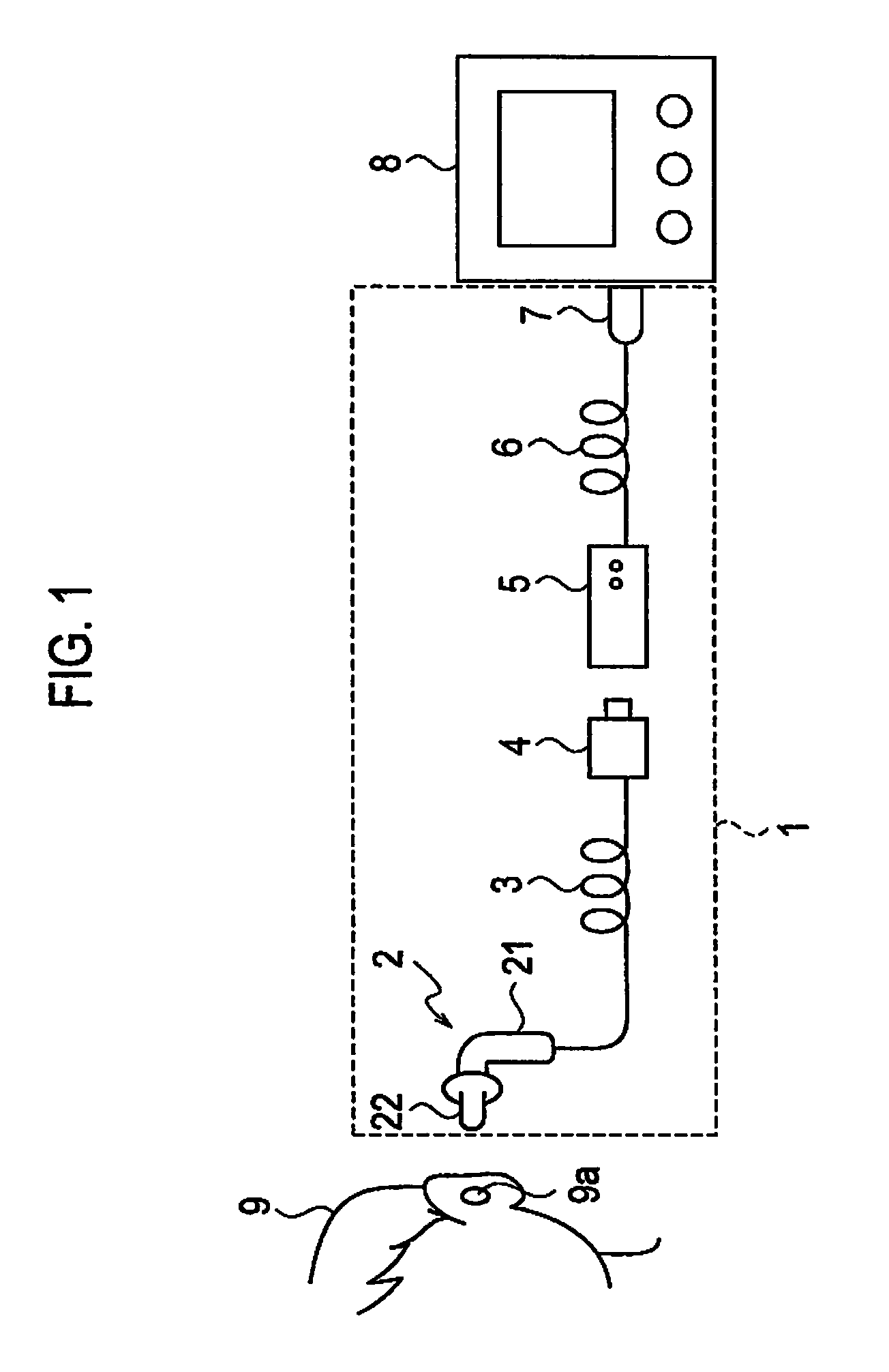
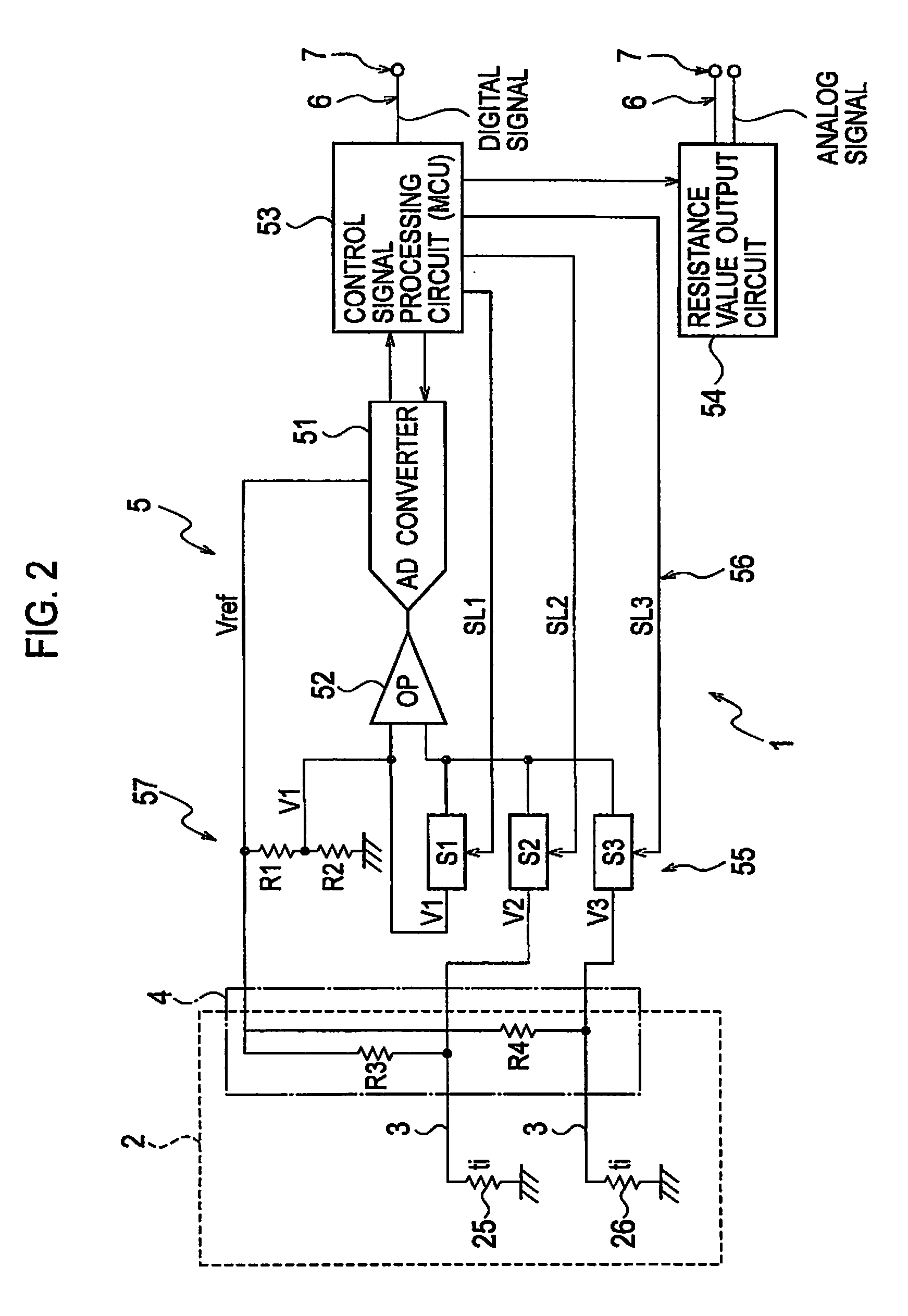
[0056]FIG. 1 illustrates a device configuration of an ear thermometer according to an embodiment of the present invention and FIG. 2 illustrates a circuit configuration thereof. As illustrated in FIG. 1, the ear thermometer 1 according to this embodiment has a probe 2 that is inserted into an ear hole of an object person, to measure the temperature of an eardrum and output a resistance value representative of the measured temperature, a cable 3 to transmit a measurement signal of the probe 2 and supply power to the probe 2, a male connector 4, a measuring apparatus 5 to perform a temperature measuring process and other control, a cable 6 connected to the measuring apparatus 5, and a female connector 7 connected to a front end of the cable 6. The female connector 7 connected to the cable 6 of the measuring apparatus 5 is connected to a monitor 8 to display a measured temperature.

[005...


PUM


Abstract

An object is to realize an ear thermometer that is configured to easily arrange a sensor in a sensor mirror and is suitable for mass production. The ear thermometer has a probe. The probe includes a probe body and a temperature measuring part joined with the probe body. The temperature measuring part includes a flange coupled with the probe body and a front end part extending from the flange, the front end part incorporating a sensor mirror. The sensor mirror includes a cylindrical holder with an internal concave reflection face, a connection shaft extending from the back of the cylindrical holder, a flexible printed circuit board with a circuit conductor of predetermined pattern, stretched in a front space of the cylindrical holder, a temperature measuring first sensor and a correcting second sensor spaced by a predetermined distance from each other in a longitudinal direction of the board and soldered to the circuit conductor on the board, and a protection cover covering a front face of the cylindrical holder. The board is electrically connected, in the temperature measuring part, to the cable passing through the probe body.

Description

TECHNICAL FIELD [0001]The present invention generally relates to a thermometer to measure the body temperature of a measuring object, and particularly, to an ear thermometer to measure a temperature of the eardrum by inserting a temperature sensing part into an ear hole and a measuring apparatus used with the ear thermometer.BACKGROUND TECHNOLOGY[0002]A typical example of a conventional ear thermometer will be explained with reference to FIGS. 15 and 16. FIG. 15 is a circuit block diagram illustrating an operation principle of the conventional ear thermometer and FIG. 16 is a vertical section of a temperature sensing part of the conventional ear thermometer. As illustrated in FIG. 15, a probe 10 of the typical conventional ear thermometer employs a thermopile 11. Generally, the thermopile produces a potential difference depending on a temperature difference between a cold junction and a hot junction (the Seebeck effect). Using the thermopile as a temperature measuring probe needs a ...

Claims


Application Information

Patent Timeline
IPC IPC(8): G01J5/00G01J5/02
CPCG01J3/0202G01J3/0243G01J5/0011G01J5/02G01J5/0205G01J5/025G01J5/028G01J5/04G01J5/048G01J5/049G01J5/08G01J5/085G01J5/14G01J2005/068H05K1/189H05K2201/09063H05K2201/10151H05K2201/10606G01J5/064A61B5/01G01J5/00
Inventor TANAKA, HIDEKI
Owner BIO ECHO NET
Why Eureka
Try Eureka