
Dose profile measurement system for clinical proton fields

a proton beam and dose profile technology, applied in the field of beam profile measurement detectors, can solve the problems that commercial solutions are not known that allow the measurement of depth dose distribution in actively delivered proton beams, and achieve the effects of reducing the number of channels required, and reducing the number of channels

Inactive Publication Date: 2010-07-08
INDIANA UNIV RES & TECH CORP
View PDF6 Cites 10 Cited by
  • Summary
  • Abstract
  • Description
  • Claims
  • Application Information

AI Technical Summary

Benefits of technology

The present invention provides two detectors that can measure the dose distribution in fields created with methods such as uniform beam scanning and energy stacking. These detectors can measure fields with lateral sizes up to 30 cm in diameter and with Spread-out Bragg Peak (SOBP) modulation up to 15 cm in water. The detectors have a spatial resolution of a few mm laterally and 1 mm or better in depth. No commercial solutions are known that allow the measurement of depth dose distributions in actively delivered proton beams. The detectors are designed based on a static array of detectors that span the entire area of interest and provide information about dose distribution in the process of beam delivery. Both detectors provide a portable measurement system with sufficient precision of measurements while minimizing the number of channels required for the task. The detectors enable the measurement of proton field profiles to which a human patient or other entity will be, or has been, exposed. The detectors provide significant time savings during measurements in actively delivered beams compared with traditional measurements using a water phantom.

Problems solved by technology

However, even the largest commercially available lateral profile detectors do not cover areas bigger than 27 cm×27 cm.
No commercial solutions are known that allow the measurement of depth dose distributions in actively delivered proton beams.

Method used


Image

  • Dose profile measurement system for clinical proton fields
  • Dose profile measurement system for clinical proton fields
  • Dose profile measurement system for clinical proton fields

Examples


Embodiment Construction

I. Materials and Methods

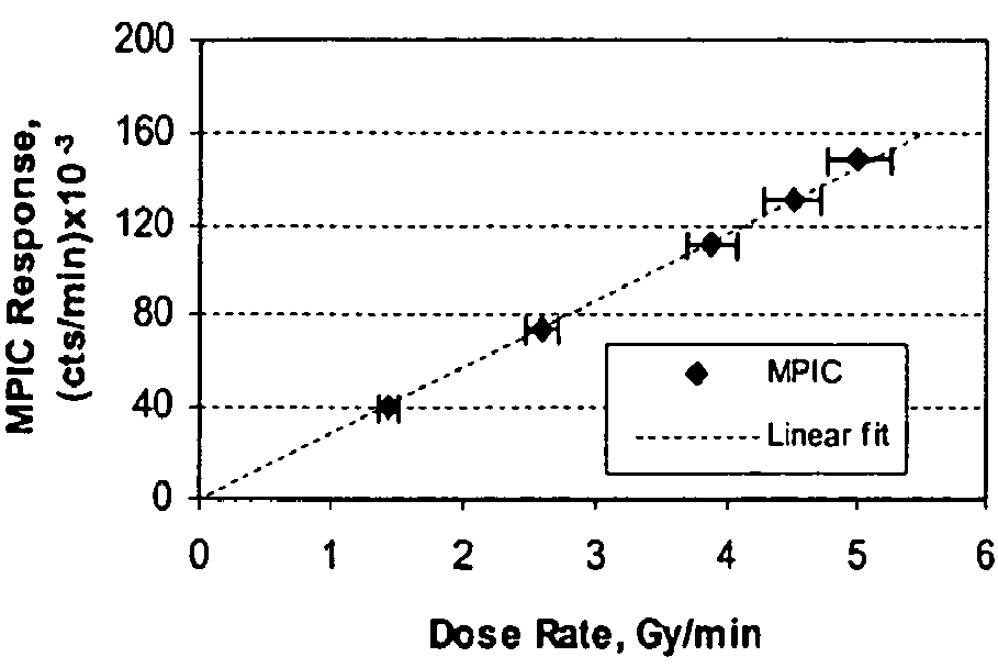
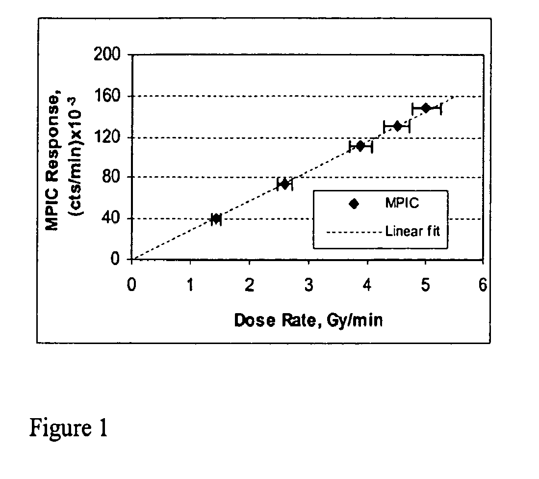
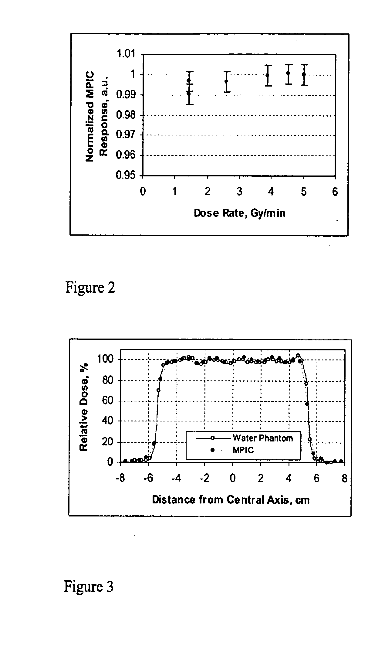
[0025]For beam commissioning and quality assurance, the two detectors function as a Multi-Pad Ionization Chamber and a Multi-Layer Ionization Chamber. Each detector can be independently positioned at the room isocenter and used for profile measurements, alone, or in combination with water equivalent plastic phantom mounted in front of the detector. Preliminary detector evaluations were conducted in a fixed beam line room with double scattering and range modular wheels. Performance tests were conducted in a room equipped with gantry and active beam delivery technology.

[0026]Beam energy (range) was controlled within ±0.1 mm by a beam delivery system that incorporates a double wedge degrader and a multilayer Faraday cup calibrated against the beam range in water. Beam intensity was controlled at the cyclotron such that an intensity of between 1 and 10 nA would be delivered to the gantry nozzle.

[0027]Depending on the scanning parameters set for a particular field...


PUM

PropertyMeasurementUnit
thicknessaaaaaaaaaa
distancesaaaaaaaaaa
lengthaaaaaaaaaa

Abstract

A beam profile measurement detector is a tool to efficiently verify dose distributions created with active methods of a clinical proton beam delivery. A Multi-Pad Ionization Chamber (MPIC) has 128 ionization chambers arranged in one plane and measure lateral profiles in fields up to 38 cm in diameter. The MPIC pads have a 5 mm pitch for fields up to 20 cm in diameter and a 7 mm pitch for larger fields, providing an accuracy of field size determination of about 0.5 mm. The Multi-Layer Ionization Chamber (MLIC) detector contains 122 small-volume ionization chambers stacked at a 1.82 mm step (water-equivalent) for depth-dose profile measurements. The MLIC detector can measure profiles up to 20 cm in depth, and determine the 80% distal dose fall-off with about 0.1 mm precision. Both detectors can be connected to the same set of electronics modules, which form the detectors' data acquisition system. The detectors operate in proton fields produced with active methods of beam delivery such as uniform scanning and energy stacking. The MPIC and MLIC detectors can be used for dosimetric characterization of clinical proton fields.

Description

RELATED APPLICATIONS[0001]This application claims the benefit of U.S. Provisional Application 60 / 942,394 filed Jun. 6, 2007, and of U.S. Provisional Application 60 / 989,582 filed Nov. 21, 2007, each of which is hereby incorporated by reference herein.FIELD OF THE INVENTION[0002]The present invention relates generally to beam profile measurement detectors for verifying dose distributions of clinical proton beam delivery.DESCRIPTION OF THE RELATED ART[0003]Active methods of beam delivery such as beam scanning, and energy stacking are becoming increasingly popular as new clinical proton facilities come in operation. As used herein, “beam scanning” is defined as any method of magnetically deflecting a beam's direction in order to cover a specified area at the treatment room isocenter. Uniform beam scanning is a method of “painting” uniformly a designated area with the beam spot, wherein the beam spot moves along a predefined continuous pattern, and without terminating the beam delivery. ...

Claims


Application Information

Patent Timeline
Patent Type & Authority Applications(United States)
IPC IPC(8): G01N27/62
CPCA61N5/1048G01T1/2935G01T1/185A61N2005/1087
Inventor NICHIPOROV, DMITRISOLBERG, KEITHWOLANSKI, MARKKLYACHKO, ALEXANDEREADS, ALAN
Owner INDIANA UNIV RES & TECH CORP
Learn More