
Engine Driven Welder and Running Gear

a technology of engine driven welders and running gears, which is applied in the direction of manufacturing tools, soldering devices, auxillary welding devices, etc., can solve the problems of large and heavy engine driven welders, high cost, and long weld cables, so as to reduce the exposure of portable engine driven welders and facilitate the user to push across uneven terrain

Active Publication Date: 2010-06-17
ILLINOIS TOOL WORKS INC
View PDF38 Cites 13 Cited by
  • Summary
  • Abstract
  • Description
  • Claims
  • Application Information

AI Technical Summary

Benefits of technology

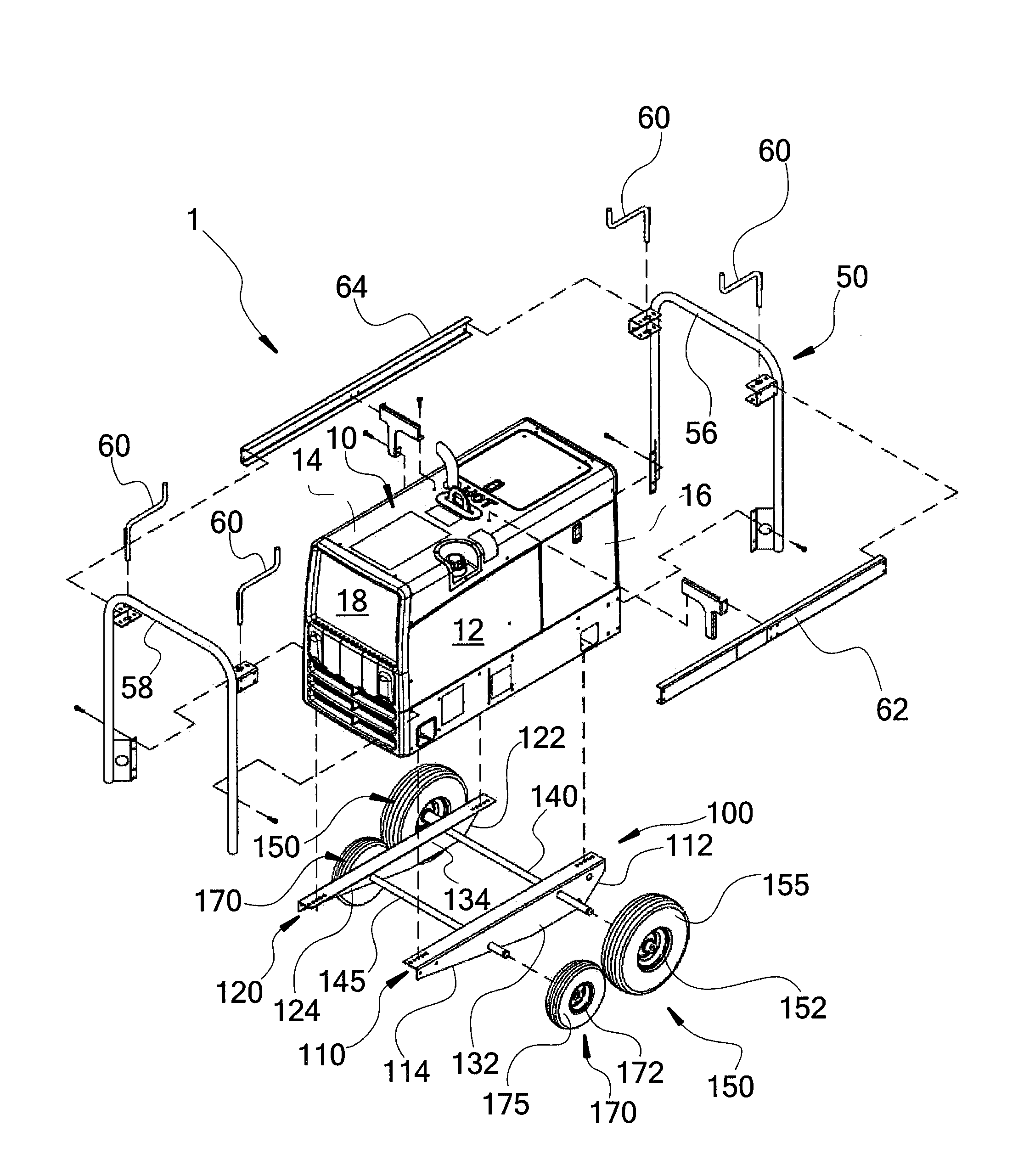
[0011]In light of the foregoing, a portable engine driven welder is provided that has a case enclosing an internal combustion engine and a welding generator, and a running gear that is attached to the case. The running gear includes a pair of rails and a pair of leading wheels connected to the rails toward the back wall of the case. A pair of trailing wheels is connected to the rails toward the front wall of the case. The leading and trailing wheels have different resiliencies, with the leading wheels being more resilient than the trailing wheels. This allows the leading wheels to act like a suspension system for the portable engine driven welder and running gear by soaking up or absorbing impacts instead of transmitting them therethrough so as to reduce exposure of the portable engine driven welder to such impacts, and making it easier for a user to push across uneven terrain.
[0012]In some aspects, the leading wheels are larger, for example, having larger diameters, than trailing wheels. The leading and trailing wheels can have central wheel segments with tires mounted thereto, and the tires on the leading wheels can have taller sidewalls heights. Some implementations have pneumatic tires and, in these implementations, the tires on the leading wheels can be inflated to a lower operating pressure or lower PSI (pounds per square inch) than the tires on the trailing wheels. Larger tire diameters, larger tires widths, taller sidewall heights, particular sidewall thickness dimensions, lower operating pressures, and / or other factors can contribute to the leading wheels having greater resiliency values than the trailing wheels.
[0013]According to yet other aspects, larger diameter leading wheels can help the leading wheels roll over obstacles instead of having to be lifted up and over. Such configuration reduces the amount of times that, or reduces the extent to which, an operator has to push down on the engine driven welder in order to lift the leading wheels upwardly to climb over obstacles. The larger leading wheels may climb up at least some such obstacles by merely rolling over them.
[0014]In some aspects, the leading wheels have larger footprints or contact patches defined between them and the underlying ground surface than do the trailing wheels. The smaller contact patches of the trailing wheels may, in some instances, improve maneuverability of the engine driven welder by allowing a user to laterally or transversely skid the trailing wheels across the underlying ground surface in order to (re)point the engine driven welder in a desired travel direction.
[0015]According to yet other aspects, the rails can include front tapering segments that extend upward and angularly, tangentially or otherwise, in front of the leading wheels. Such front tapering segments may protect the leading wheels from impacting certain relatively tall obstructions. The front tapering segments may further provide skid or ramp-like structures than allow users to slide the engine driven welder up tall obstacles before the leading wheels can engage and roll over such obstacles. The front tapering segments may cooperate with the leading wheels, such that obstacles that would otherwise be contacted at or near a front axle height of the leading wheels, which would be difficult for the wheels to roll over, can be at least partially slid up, pushed up, glanced up, or skidded up, by way of the front tapering segments, so that such obstacle then contacts a lower portion of the leading wheels. This can make the obstacle easier to roll or climb over, at that point, by contacting portions of the leading wheels that are spaced further below their axis of rotation, which makes rotating the leading wheels easier.

Problems solved by technology

Engine driven welders can be quite large and heavy, whereby they are at times installed upon a vehicle such as a work truck that is driven to the jobsite.
Such long weld cables can be heavy and expensive.

Method used


Image

  • Engine Driven Welder and Running Gear
  • Engine Driven Welder and Running Gear
  • Engine Driven Welder and Running Gear

Examples


Embodiment Construction

[0022]FIGS. 1 and 2 show portable engine driven welders, e.g., welders 1, each including a protective cage 50 and a running gear 100. The welder 1 includes an internal combustion engine and a welding generator 7 that are housed within a case 10. A suitable such welder 1 can include any of the Bobcat™, Legend®, and Trailblazer® Series from the Miller Electric Manufacturing Company, in Appleton, Wis. The case 10 includes a bottom wall 11, a pair of sidewalls 12, 14 that extend upwardly from side edges of the bottom wall 11. A back wall 16 extends between and interconnects the sidewalls 12, 14 at a back end of the case. A front wall 18 extends between and interconnects the sidewalls 12, 14 at a front end of the case. Front wall 18 houses the controls for the welder 1 and typically faces away from a direction of travel, so that they are less susceptible to impact-induced damage than they would be if they faced toward the travel direction.

[0023]Still referring to FIGS. 1 and 2, protectiv...


PUM

PropertyMeasurementUnit
diametersaaaaaaaaaa
diametersaaaaaaaaaa
resiliencyaaaaaaaaaa

Abstract

A portable engine driven welder is provided that has a case enclosing an internal combustion engine and a welding generator, and a running gear that is attached to the case. The running gear includes a pair of rails and a pair of leading wheels connected to the rails toward the back wall of the case. A pair of trailing wheels is connected to the rails toward the front wall of the case. The leading and trailing wheels have different resiliency values with the leading wheels being more resilient or flexible than the trailing wheels. This allows the leading wheels to act like a suspension system for the portable engine driven welder and running gear by soaking up or absorbing impacts instead of transmitting them therethrough so as to reduce exposure of the portable engine driven welder to such impacts.

Description

CROSS-REFERENCE TO RELATED APPLICATIONS[0001]This utility patent application claims the benefit of and priority to U.S. provisional application 61 / 122,996, filed Dec. 16, 2008, entitled CART FOR A WELDER; WELDER / CART COMBINATION, which is herein expressly incorporated by reference in its entirety, for all purposes.BACKGROUND OF THE INVENTION[0002]1. Field of the Invention[0003]The present invention relates to engine driven welders and, more specifically, to engine driven welders having running gears to facilitate movement of such engine driven welders.[0004]2. Discussion of the Related Art[0005]A need to move welding equipment has been long recognized. Various running gears have been provided for suitably moving welding equipment around in a welding shop or other fabricating facility. Such facilities usually have substantially flat floor surfaces, whereby caster-like wheels have been successfully implemented into running gears for rolling the welding equipment across these flat floo...

Claims


Application Information

Patent Timeline
Patent Type & Authority Applications(United States)
IPC IPC(8): B23K9/10B62D21/02
CPCB23K37/0294B23K9/1006
Inventor LAITALA, JOHN P.
Owner ILLINOIS TOOL WORKS INC
Learn More