
Gas recovery process

a gas recovery and gas technology, applied in the direction of separation processes, oxygen/ozone/oxide/hydroxide, dispersed particle separation, etc., can solve the problems of psa/vsa being generally not considered a viable technology, and requiring the energy intensive liquefaction of the whole feed stream

Inactive Publication Date: 2010-06-10
LINDE LLC
View PDF12 Cites 0 Cited by
  • Summary
  • Abstract
  • Description
  • Claims
  • Application Information

AI Technical Summary

Benefits of technology

"The present invention provides methods for recovering a gas component from a gas mixture with higher concentration and yield. The methods involve using a concentration unit and a recovery unit in combination. The concentration unit generates an external product stream with a higher concentration of the gas component and an external waste stream with a lower concentration of the gas component. The recovery unit recovers the gas component from the external waste stream and generates an external product stream with a higher concentration of the gas component. The methods can be used in space applications to recover oxygen from mixtures with nitrogen and other inert gases. The invention allows for the recovery of a gas component from a gas mixture with low concentration levels and can be used in various industrial applications."

Problems solved by technology

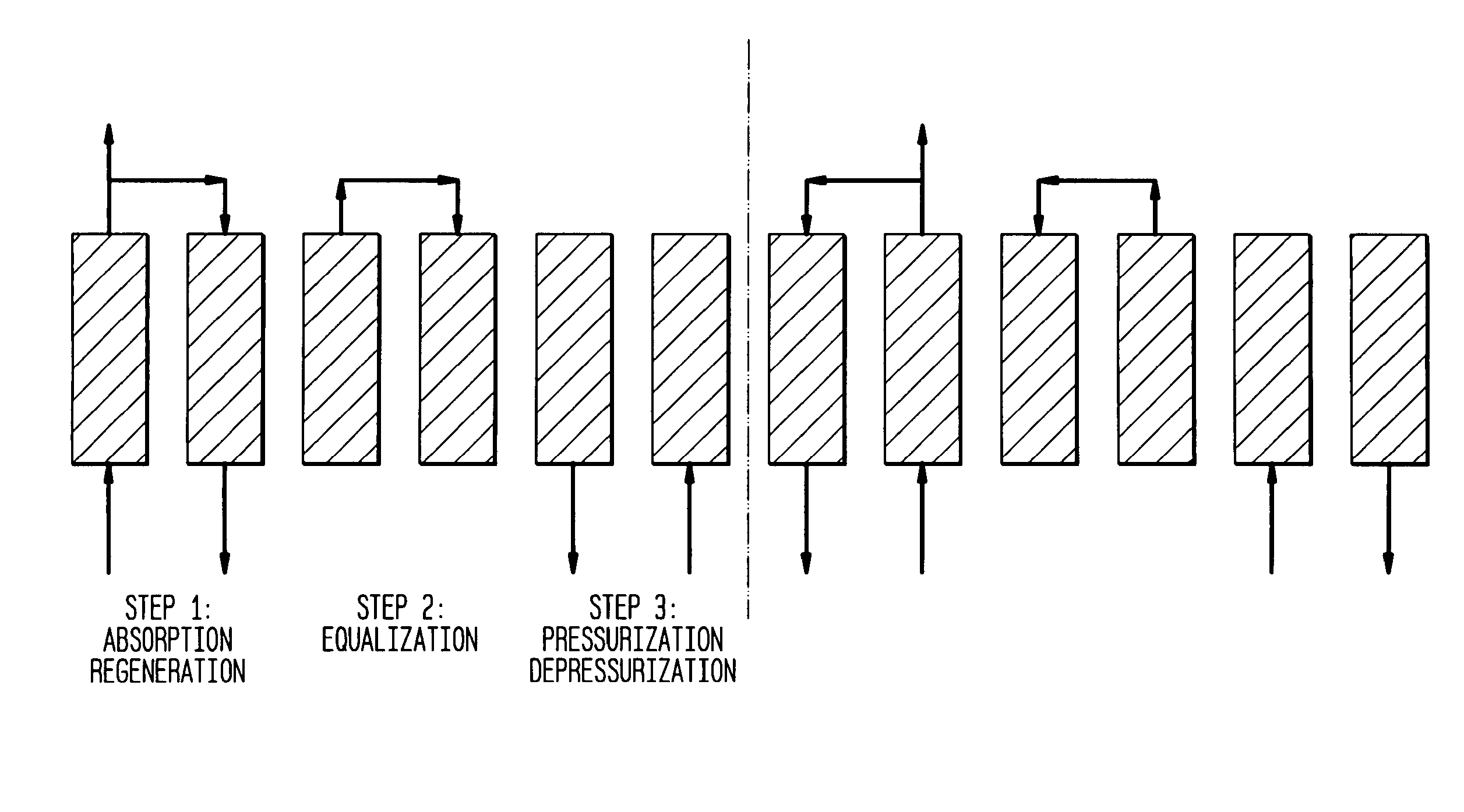
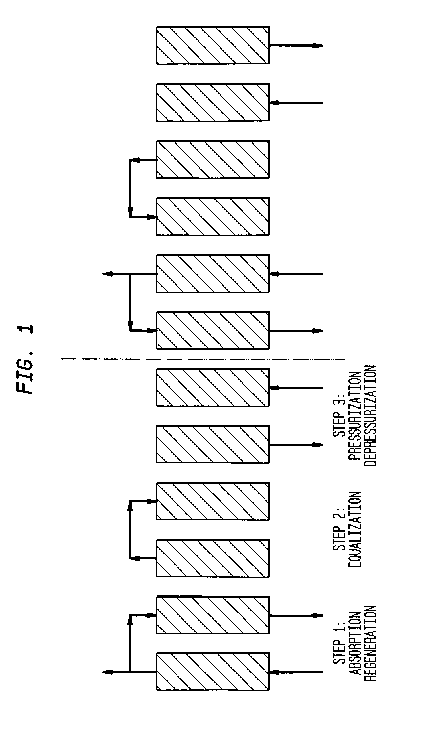
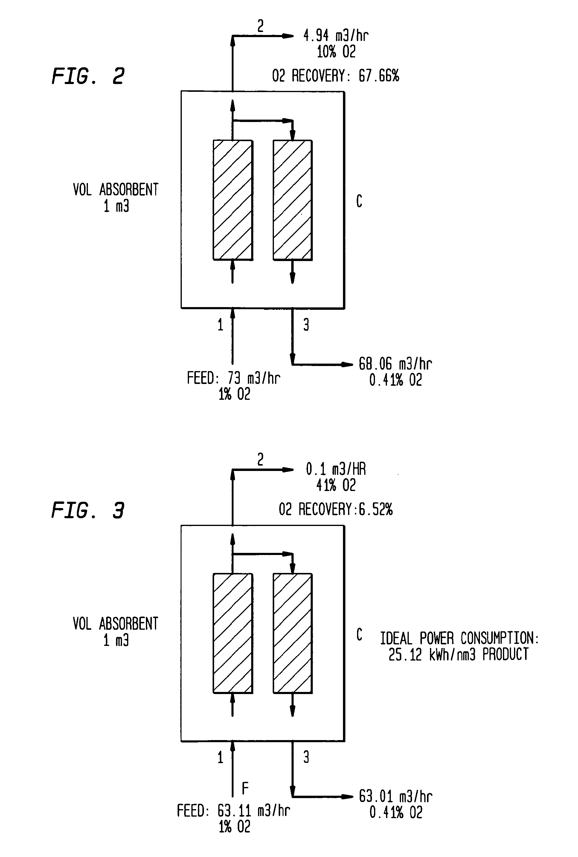
PSA / VSA is generally not thought to be a viable technology for the concentration to high purity of a desired gaseous product from a very dilute feed stream, let alone for achieving this aim at high recovery.
Cryogenic distillation can give very high purity products dependent of the equilibrium vapor pressure data for the components to be separated, but in the case of a very dilute feed gas stream this will require the energy intensive liquefaction of the whole feed stream.

Method used


Image

  • Gas recovery process
  • Gas recovery process
  • Gas recovery process

Examples


example 6

[0052]FIG. 7, shows schematically the addition of a recovery (R) unit to the system depicted in FIG. 6 with again the goal to increase the oxygen concentration of the feed from 2% to 22%. The feed, product and waste streams of the recovery unit are numbered 101, 102 and 103, respectively. The recovery VSA unit is in series with the concentration VSA unit and connected with recycle from the concentration unit. In detail, the waste stream from the concentration unit (line 3) is connected to the input of the recovery unit (line 101) and the product stream from the recovery unit (line 102) is mixed with the external feed (F) to provide the feed to the concentration unit (line 1). The results of the simulation show that the total recovered oxygen under these conditions would be 95%. This Example is for illustrative purposes demonstrating that the addition of recovery unit leads to a significant increase in the yield of the desired product. To fully achieve the targets of this invention, ...

example 7

[0053]In FIG. 8, there is shown a system of the current invention, in which a two-stage VSA recovery unit (comprising recovery stages R1 and R2) is combined with two-stage VSA concentration unit (C1 and C2) with recycle of the external waste stream from the concentration unit (line 3) to the external input of the recovery unit (line 110) and connection of the external output of the recovery unit (line 112) to the external input of the concentration unit (line 1) The results of the simulation show an oxygen purity of 95% can be achieved at an overall yield of 91.8% under these conditions from a feed stream with an oxygen concentration of 1%. Comparison of the results from this Example with those from Examples 1 to 4 clearly demonstrates the advantages of the current invention over prior art PSA or VSA systems in obtaining a valuable product at high purity and high yield from a dilute mixture of this product with other gases.

example 8

[0054]In FIG. 9, there is described a system of the current invention that utilizes a single stage VSA recovery unit (R) in combination with a 4-stage VSA concentration unit (C1-C4) in order to recover Ar-40 which is present at 0.1% level in waste gas from helium production. The lines are numbered analogously to those in the earlier Figures. The results of the simulation showed that the very valuable Ar-40 isotope could be recovered at 99% purity with an overall yield of 89% from this very dilute source.


PUM

PropertyMeasurementUnit
temperaturesaaaaaaaaaa

Abstract

A method for concentrating a single gas component from a gas mixture is disclosed. The method utilizes concentration units and recovery units to concentrate the single gas component which is often at very low concentrations in the gas mixture. This method allows for the recovery of a valuable gas depending upon application such as oxygen and Ar-40.

Description

BACKGROUND OF THE INVENTION[0001]This application claims priority from International Application Serial No. PCT / US2007 / 088078 filed 19 Dec. 2007 (published as WO 2008 / 079858 A1, with publication date 3 Jul. 2008), which claims priority from U.S. Provisional Patent Application Ser. No. 60 / 876,067, filed Dec. 20, 2006.[0002]Simple 1, 2 or 3-bed pressure swing adsorption or vacuum swing adsorption separation units (PSAs and VSAs, respectively) utilizing relatively simple cycles are widely utilized for bulk separations of gases where moderate quantities, moderate yields and moderate purities of, e.g., nitrogen or oxygen from air are required. H2 is commercially purified to >99% purity using PSA units that comprise many beds (e.g., 6 to 12) and that use more complex cycles with multiple equalizations. H2 recovery levels of 80 to 90% can be realized in this way.[0003]In general, feed gas compositions containing at least 10 to 20% concentration of the desired product, preferably more, a...

Claims


Application Information

Patent Timeline
Patent Type & Authority Applications(United States)
IPC IPC(8): B01D53/047B01D53/02
CPCB01D53/0476C01B2210/0046B01D2257/104B01D2257/11B01D2259/40013B01D2259/40028B01D2259/40035B01D2259/40043B01D2259/4006B01D2259/40062B01D2259/40064B01D2259/404B01D2259/4065B01D2259/4067C01B13/0259C01B21/045C01B21/0461C01B21/0466C01B23/0052C01B23/0063C01B23/0068C01B2210/0026C01B2210/0029C01B2210/0031C01B2210/0034B01D2253/108
Inventor LACAVA, ALBERTO I.FITCH, FRANK R.SHIRLEY, ARTHUR I.
Owner LINDE LLC
Learn More