
Method for improvement of beam quality and wavelength stabilized operation of a semiconductor diode laser with an extended waveguide

a wavelength stabilized, semiconductor diode technology, applied in the direction of lasers, lasers, optical resonator shape and construction, etc., can solve the problems of reduced device brightness, highly undesirable localized mode, etc., to improve wavelength stabilization operation, enhance device wavelength selectivity, and suppress light output power emitted

Active Publication Date: 2010-06-03
VI SYST GMBH
View PDF25 Cites 4 Cited by
  • Summary
  • Abstract
  • Description
  • Claims
  • Application Information

AI Technical Summary

Benefits of technology

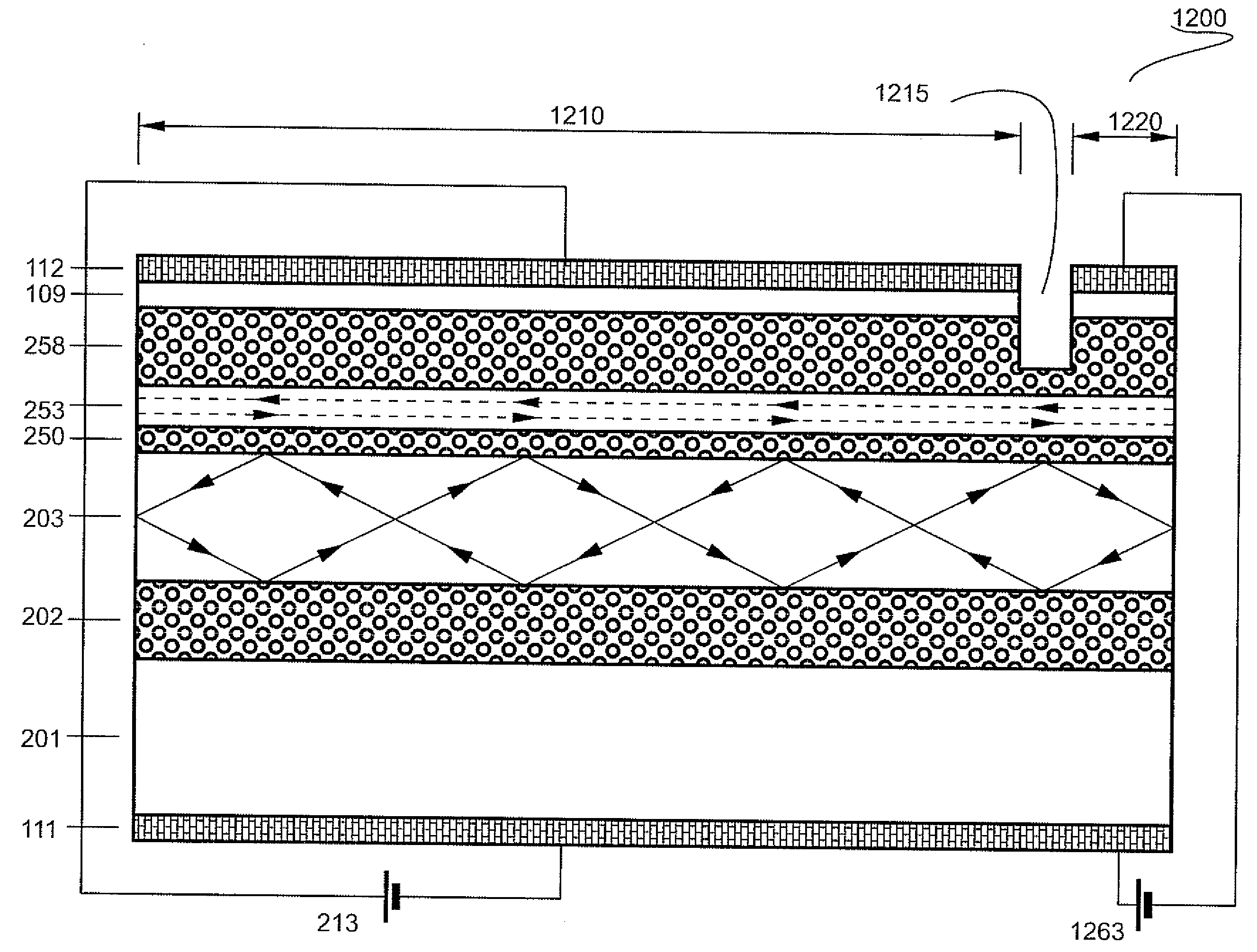
[0051]In yet another embodiment of the present invention, the resonator length is specifically selected to be equal to the length of the return path of the tilted wave multiplied by a rational number such that the tilted wave in the broad waveguide forms a closed loop. In this embodiment however, the selection of the resonator length allows enhancement of the wavelength selectivity of the device thus improving the wavelength-stabilized operation.
[0052]In a further embodiment of the present invention, a tilted wave laser further comprises an unpumped section. This is preferably located close to the front facet, thus suppressing the light output power emitted from the narrow waveguide in a broad angular spectrum. This enhances the fraction of the light output power concentrated in the narrow lobes.
[0053]In another embodiment of the present invention, an unpumped section is configured such to enhance the wavelength selectivity of the device.

Problems solved by technology

In both cases lasing in a localized mode is highly undesirable due to the resulting reduced brightness of the device and disadvantages related to the catastrophic optical damage of the mirrors of the facet for the localized mode and needs to be suppressed.

Method used


Image

  • Method for improvement of beam quality and wavelength stabilized operation of a semiconductor diode laser with an extended waveguide
  • Method for improvement of beam quality and wavelength stabilized operation of a semiconductor diode laser with an extended waveguide
  • Method for improvement of beam quality and wavelength stabilized operation of a semiconductor diode laser with an extended waveguide

Examples


Embodiment Construction

[0109]FIG. 9 demonstrates a possible extension of the tilted wave laser. FIG. 9(a) shows schematically a tilted wave laser (900) similar to the one of FIG. 5(b). Light propagates in the broad waveguide (203) in a tilted mode (920) and comes out from the broad waveguide (945) and from the narrow waveguide (941). FIG. 9(b) shows schematically a tilted wave laser according (950) to one embodiment of the present invention. The narrow waveguide and the broad waveguide are selected such that the leakage angle defined by the equation

ϑleakage=cos-1(neffnarrowWGnbroadWG),(Eq.1)

where neffnarrow WG is the effective refractive index of the optical mode in the narrow waveguide, and nbroad WG is the refractive index of the broad waveguide, exceed the angle of the total internal reflection at the semiconductor / air interface,

ϑleakage>sin-1(1nbroadWG).(Eq.2)

Then light in the broad waveguide (203), propagating in a tilted mode (970) will exhibit the total internal reflection at the semiconductor / a...


PUM


Abstract

A method is disclosed for improving the functionality of a semiconductor diode laser with an extended vertical waveguide, wherein the active medium is located close to the top cladding layer of the waveguide, and the laser aims to emit light in a narrow beam with high brightness and / or to operate in the wavelength-stabilized regime. The goal is to suppress parasitic optical modes localized close to the top cladding layer of the waveguide. Unpumped sections and groves perpendicular to the stripe serve to suppress these parasitic modes. Deep (preferably a few tens of micrometers) groves parallel to the stripe suppress parasitic emission of light and the feedback in the closed lateral modes. In a tilted wave laser the longitudinal resonator can be preferably configured to have a selected length to ensure closed loops formed in the longitudinal direction by the tilted wave.

Description

REFERENCE TO RELATED APPLICATIONS[0001]This application claims an invention which was disclosed in[0002]U.S. Provisional Patent Application No. US61 / 118,550, filed Nov. 28, 2008, entitled “METHOD FOR IMPROVEMENT OF BEAM QUALITY AND WAVELENGTH STABILIZED OPERATION OF TILTED WAVE SEMICONDUCTOR DIODE LASERS” and[0003]U.S. Provisional Patent Application No. US61 / 245,326, filed Sep. 24, 2009, entitled “METHOD FOR SUPPRESSION OF PARASITIC EMISSION IN A SEMICONDUCTOR DIODE LASER WITH AN EXTENDED”.[0004]The aforementioned applications are hereby incorporated herein by reference.BACKGROUND OF THE INVENTION[0005]1. Field of the Invention[0006]The invention pertains to the field of semiconductor optoelectronic devices. More particularly, the invention pertains to high-power high-brightness semiconductor diode lasers with a narrow beam divergence and to wavelength-stabilized semiconductor diode lasers.[0007]2. Description of Related Art[0008]There is a need in high-power power semiconductor dio...

Claims


Application Information

Patent Timeline
IPC IPC(8): H01S5/026H01L33/00
CPCH01S5/0265H01S5/028H01S5/1017H01S5/1021H01S5/1032H01S5/1082H01S2301/08H01S5/16H01S5/2004H01S5/2027H01S5/2036H01S5/22H01S5/3213H01S5/14
Inventor SHCHUKIN, VITALYLEDENTSOV, NIKOLAI
Owner VI SYST GMBH
Learn More