
Differential-pressure sensor system and corresponding production method

Inactive Publication Date: 2010-06-03
ROBERT BOSCH GMBH
View PDF6 Cites 18 Cited by
  • Summary
  • Abstract
  • Description
  • Claims
  • Application Information

AI Technical Summary

Benefits of technology

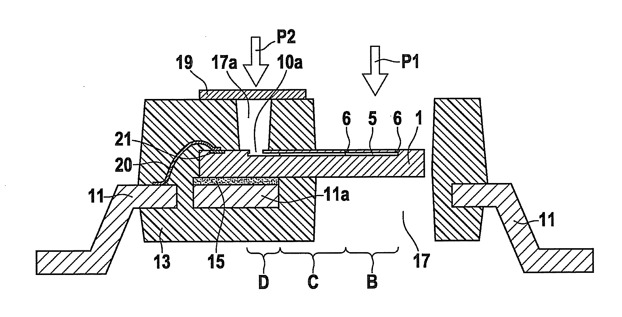
[0013]In contrast to the conventional design approaches, the differential-pressure sensor system according to the present invention and the corresponding production method may have the advantage that they allow for a construction that is simple, cost-effective, and insensitive to environmental influence. There are advantages with regard to low packaging costs during molding-in. Compared to an absolute pressure sensor without a second pressure connection, except for an additional silicon separation step to open a second pressure access opening, no further process steps are required.
[0014]The etching step for opening the second pressure access opening does not have to be performed through the entire wafer, but rather only through the thickness of the diaphragm. This saves process time. The potential clogging of the connection channel from the diaphragm cavity to the second pressure access opening by particles in the medium may be prevented by a large-area, fine-grid filter sieve or mesh.
[0015]The example construction according to the present invention is resistant to media, since the electric connections (typically made of aluminum) are protected by molding substances. Only surfaces made of silicon or silicon nitride (passivation) may be reached by the pressure medium. Silicon or silicon nitride, and thus the entire sensor, is particularly resistant to media. A gel for passivating the electrical chip connections (bond pads) is not necessary. One particular advantage is therefore a very low cross sensitivity to acceleration, and usability at higher pressures. In sensors protected by gel, the structure of the gel would be destroyed in the event of sudden drops in pressure, by small gas bubbles that form in the gel in the process (similar to aeroembolism). A monocrystalline silicon diaphragm may be produced. One particular advantage of it is the high mechanical strength or the high K factor of piezo-resistors that are doped in it. Existing processes for producing pressure sensors may be retained, for the most part. The projecting chip allows for a good stress buffer from the sensor diaphragm. Mechanical stress is broken down through the spatial separation of the mounting region from the diaphragm region. The electric initial testing in the wafer composite is possible, and a band adjustment is possible after the mounting. The geometry of the diaphragm region may be configured as desired, but preferably has a square, rectangular or round design.

Problems solved by technology

This saves process time.

Method used


Image

  • Differential-pressure sensor system and corresponding production method
  • Differential-pressure sensor system and corresponding production method
  • Differential-pressure sensor system and corresponding production method

Examples


Embodiment Construction

[0023]In the figures, like reference numerals designate like or functionally equivalent components.

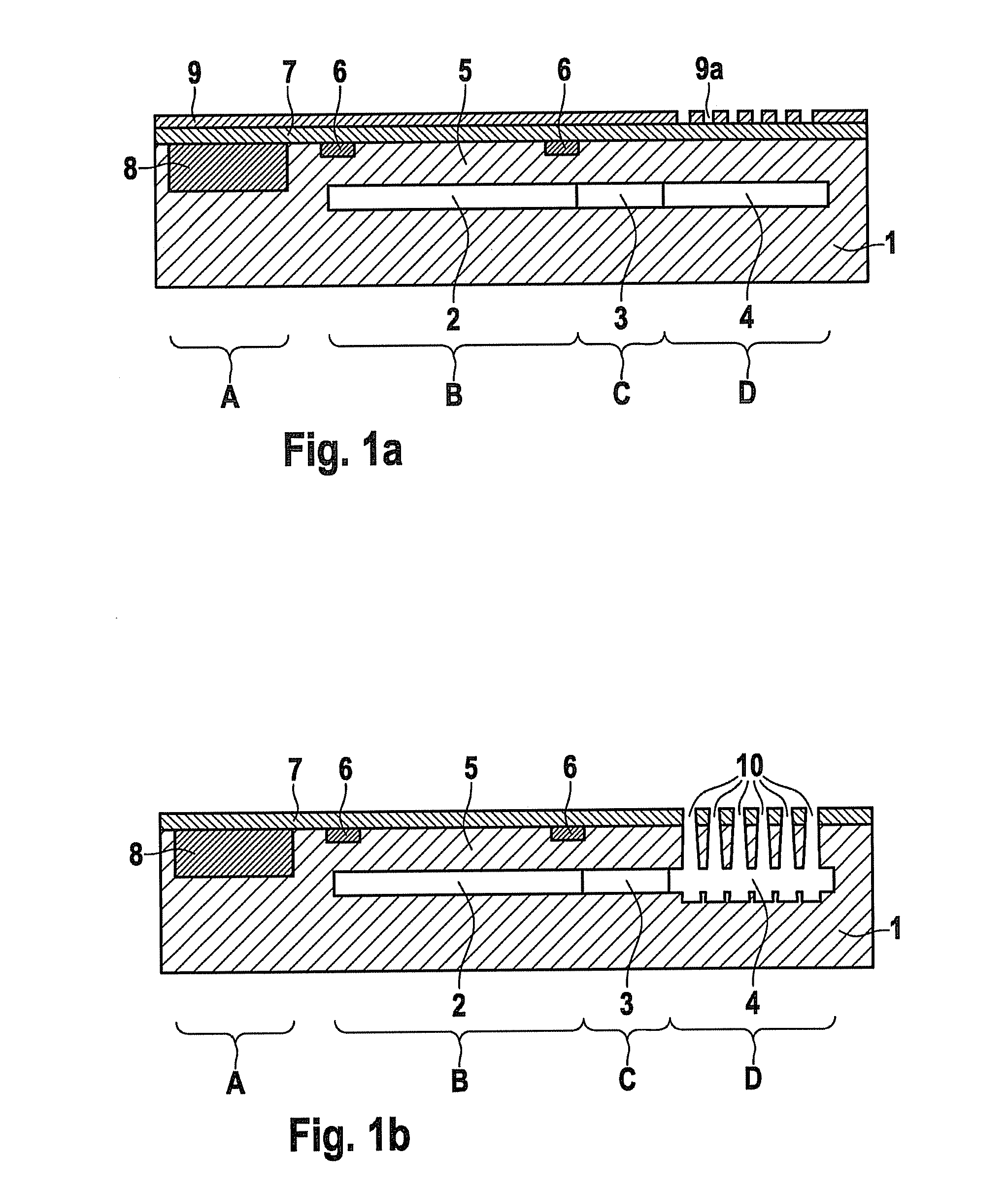
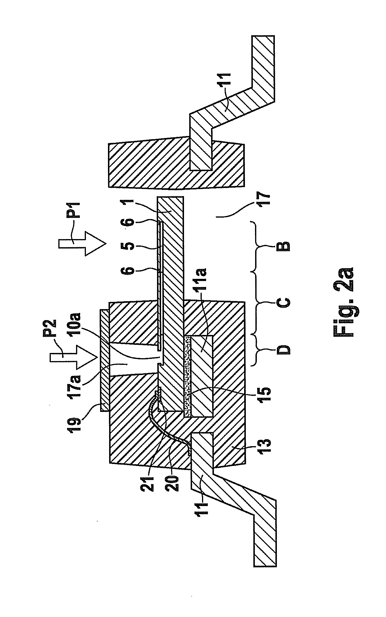
[0024]FIGS. 1a, b show schematic sectional views of a part of the process for producing a micromechanical silicon semiconductor chip system having an integrated differential-pressure sensor, which may be used in the differential-pressure sensor system according to the present invention.

[0025]In FIGS. 1a, b reference numeral 1 labels a silicon semiconductor chip having an evaluation circuit region A, a measuring pressure access region or application region B, a connection channel region C, and a reference pressure access region or application region D.

[0026]A diaphragm 5, under which a diaphragm cavity 2, a connection channel 3, and a reference pressure access space 4 have been produced, are produced in accordance with a method described in International Patent Application No. WO 02 / 02458 A1, for example. Piezoresistive resistors 6 are provided on the upper side of diaphragm 5, whose el...


PUM

PropertyMeasurementUnit
Pressureaaaaaaaaaa
Angleaaaaaaaaaa

Abstract

A differential-pressure sensor system and a corresponding production method. The differential-pressure sensor system includes: a differential-pressure sensor chip having a first pressure application region for applying a first pressure, as pressure to be detected, to the differential-pressure sensor chip, and a second pressure application region for applying a second pressure, as reference pressure, to the differential-pressure sensor chip; a housing that partially surrounds the differential-pressure sensor chip; the housing having a through hole, through which the first pressure application region is exposed to the outside; and the housing having an input opening, through which the second pressure application region is exposed to the outside.

Description

FIELD OF THE INVENTION[0001]The present invention relates to a differential-pressure sensor system and a corresponding production method.[0002]Although applicable to any semiconductor chip system, the present invention as well as the problem underlying it are explained with respect to a micromechanical silicon semiconductor chip system having an integrated differential-pressure sensor.BACKGROUND INFORMATION[0003]German Patent Application No. DE 10 2004 051 468 A1 describes a method for mounting semiconductor chips, which has the following steps:[0004]providing a semiconductor chip having a surface that has a diaphragm region and a peripheral region, the peripheral region having a mounting region, and a cavity being situated underneath the diaphragm region, which cavity extends into the mounting region and ends there in an opening;[0005]providing a substrate that has a surface having a cut-out;[0006]mounting the mounting region of the semiconductor chip in flip-chip technology on the...

Claims


Application Information

Patent Timeline
IPC IPC(8): H01L29/84B29C45/14
CPCG01L15/00G01L19/141H01L2224/48091H01L2224/48137G01L13/025H01L2224/48472H01L2224/73265H01L2924/10253H01L2224/48247H01L2924/00014H01L2924/00H01L2924/1815
Inventor BENZEL, HUBERT
Owner ROBERT BOSCH GMBH
Learn More