
Localized surface plasmon resonance sensing system, appartatus, method thereof

a plasmon resonance and sensing system technology, applied in the field of lspr sensing system, apparatus, can solve the problems of difficult miniaturization, difficult to meet the needs of small-scale, high cost, etc., and achieve the effects of promoting sensitivity, and reducing the size of the lspr sensing system

Active Publication Date: 2010-05-27
INSTANT NANOBIOSENSORS CO LTD
View PDF8 Cites 22 Cited by
  • Summary
  • Abstract
  • Description
  • Claims
  • Application Information

AI Technical Summary

Benefits of technology

The present invention is related to a localized surface plasmon resonance sensing system and method that uses an optical fiber and noble metal nano-particles to detect changes in the surrounding environment. The system is designed to be highly sensitive, portable, and disposable. It can be easily fabricated and constructed with simple optical designs and requires minimal sample consumption and reagents. The system includes a light source, optical fiber, and a micro-fluidic chip with noble metal nano-particles integrated within it. The chip is designed to accommodate a sample and drive it to contact with the noble metal nano-particles for analysis. The system can detect changes in the refractive index of the surrounding medium and the elastic scattered light from the nano-particles. The invention provides a solution for promoting sensitivity and reducing analysis time and consumption of samples and reagents.

Problems solved by technology

However, light in the sample medium cannot naturally excite PSPR and a high refractive index prism or grating is required for coupling.
Moreover, because PSPR is an extrinsic resonance phenomenon, the PSPR sensor requires complicated optical setup and is bulky in size and thus is difficult to be miniaturized and expensive to afford.

Method used


Image

  • Localized surface plasmon resonance sensing system, appartatus, method thereof
  • Localized surface plasmon resonance sensing system, appartatus, method thereof
  • Localized surface plasmon resonance sensing system, appartatus, method thereof

Examples


Embodiment Construction

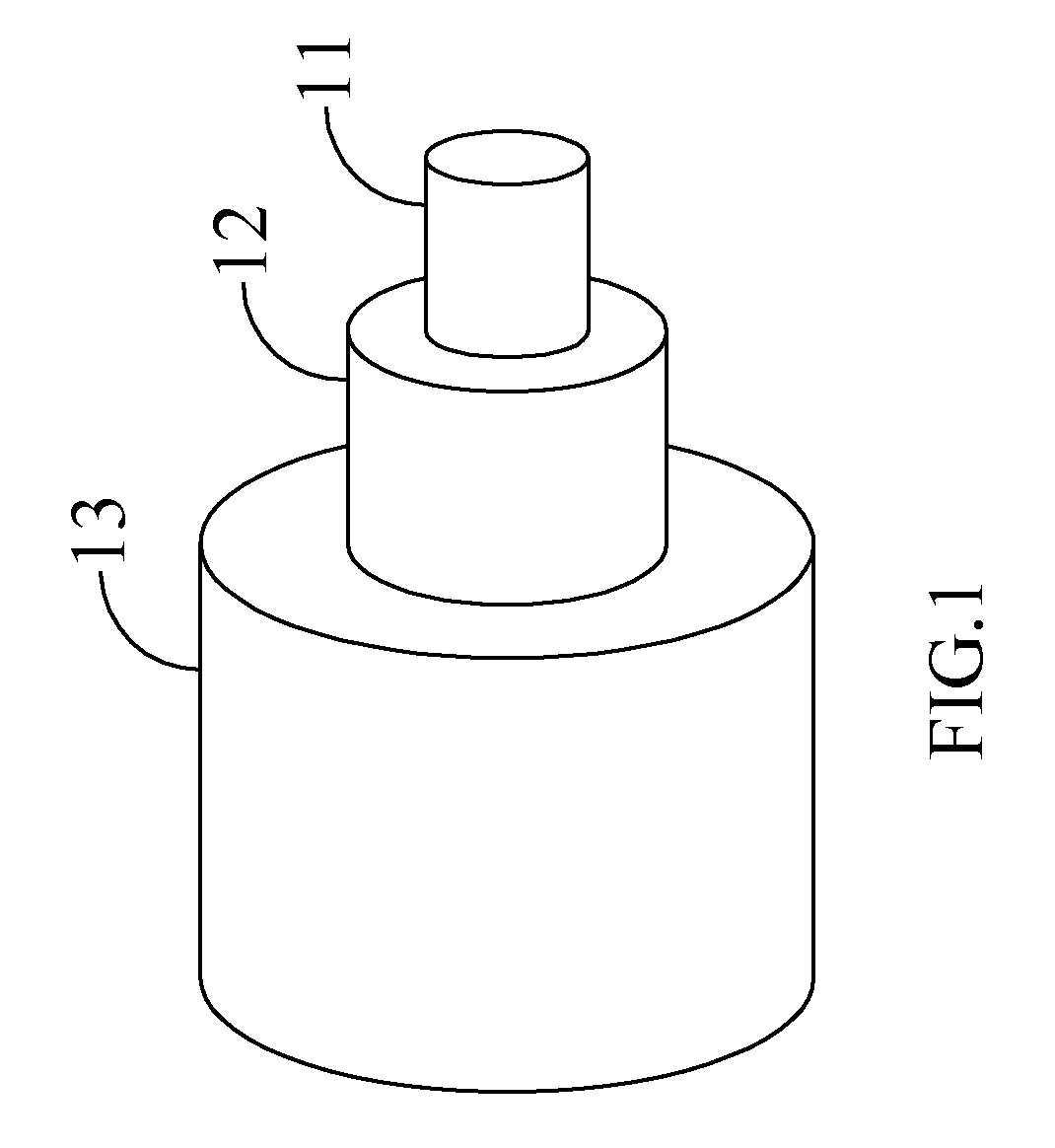
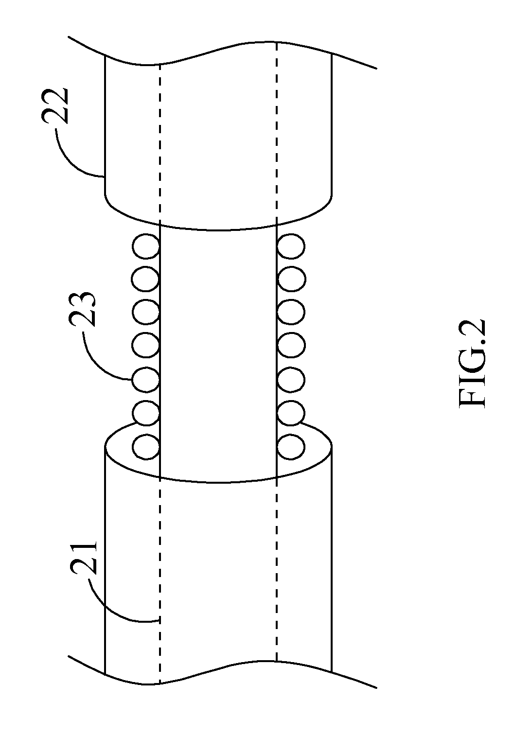
[0027]Referring to FIG. 1 for a schematic view showing construction of an optical fiber cable, the cable is essentially comprised of three layers, respectively the innermost a core 11, a cladding 12 in the middle, an outermost buffer 13 with materials and functions different from one another. As illustrated in FIG. 2 for a schematic view showing that a plurality of noble metal nano-particles 23 are disposed on the unclad portion of an optical fiber. The plurality of noble metal nano-particles 23 are gold nano-particles or silver nano-particles. The optical fiber comprises a stripped area formed by partially removing the cladding 22 of the optical fiber, then the plurality of noble metal nano-particles 23 are disposed on the core 21 of the optical fiber. The noble metal nano-particles 23 are substantially separated from each adjacent noble metal nano-particles such that the conductivity of the noble metal nano-particle submonolayer is smaller than that of the metal film.

[0028]Please ...


PUM

PropertyMeasurementUnit
conductivityaaaaaaaaaa
diameteraaaaaaaaaa

Abstract

A sensing system comprises a light source, an optical fiber, a plurality of noble metal nano-particles, a micro-fluidic module and a photo detector. The optical fiber couples an incident light. The plurality of noble metal nano-particles are disposed on a surface of the optical fiber to form a noble metal nano-particle submonolayer, the noble metal nano-particles are substantially separated from each adjacent noble metal nano-particles such that the conductivity of the noble metal nano-particle submonolayer is smaller than that of a metal film. The micro-fluidic module accommodates the optical fiber and a sample, and the sample is driven to contact with the noble metal nano-particles. The photo detector detects an emergent light from the optical fiber. When the incident light interacts with the noble metal nano-particles, a signal derived from localized surface plasmon resonance in form of attenuated light or elastic scattered light is outputted through the photo detector.

Description

CROSS-REFERENCE TO RELATED APPLICATIONS[0001]This application claims priority to, and is a Continuation-in-part of, U.S. patent application Ser. No. 11 / 558,850, filed on Nov. 10, 2006, now pending, which claims priority from Taiwan Patent Application No. 094139668 filed on Nov. 11, 2005, which are hereby incorporated by reference in their entirety.[0002]Although incorporated by reference in its entirety, no arguments or disclaimers made in the parent application apply to this divisional application. Any disclaimer that may have occurred during the prosecution of the above-referenced application(s) is hereby expressly rescinded. Consequently, the Patent Office is asked to review the new set of claims in view of all of the prior art of record and any search that the Office deems appropriate.BACKGROUND OF THE INVENTION[0003](a) Field of the Invention[0004]The present invention is related to a localized surface plasmon resonance (LSPR) sensing system with noble metal nano-particles on a...

Claims


Application Information

Patent Timeline
Patent Type & Authority Applications(United States)
IPC IPC(8): G01N21/55
CPCB01L3/5027B82Y15/00G02B6/0229G01N21/554G01N21/7703B82Y20/00
Inventor CHAU, LAI-KWANHSIEH, WEN-HSINHSU, WEI-TINGCHEN, PO-LIANG
Owner INSTANT NANOBIOSENSORS CO LTD
Learn More