
Cache Stashing Processor Control Messages

a control message and cache technology, applied in the field of digital processing devices, can solve the problems of reducing the average cpi of the processor, lowering execution performance, and reducing the execution time of the program, so as to reduce the dependence on latency bound pio operations, improve processor instruction execution performance, and reduce the overhead

Inactive Publication Date: 2010-05-20
MACOM CONNECTIVITY SOLUTIONS LLC
View PDF7 Cites 16 Cited by
  • Summary
  • Abstract
  • Description
  • Claims
  • Application Information

AI Technical Summary

Benefits of technology

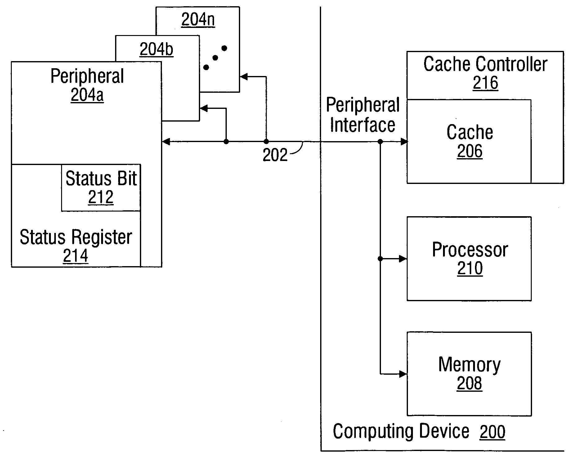
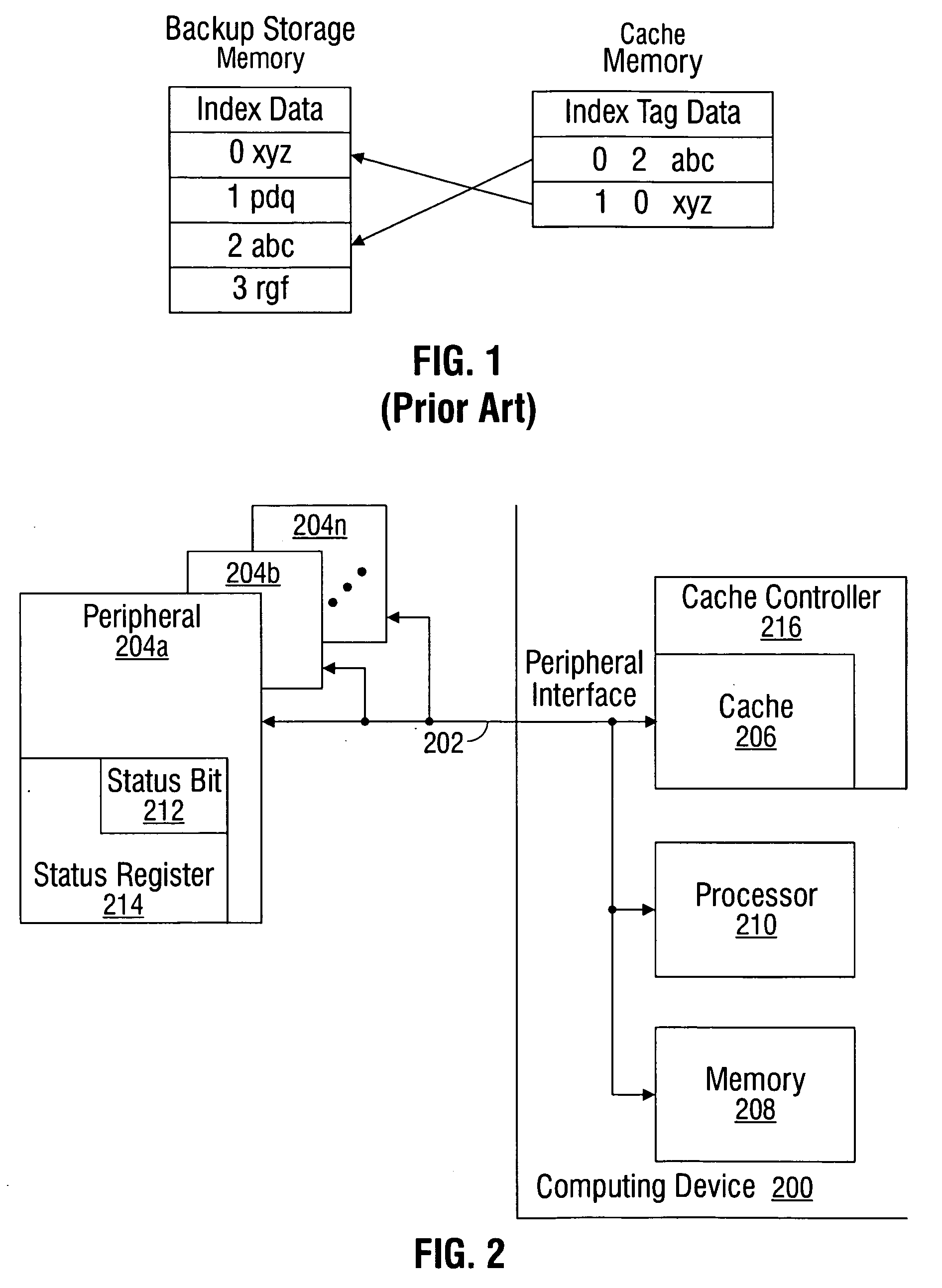
[0025]The caching system disclosed herein extends the concept of data stashing to permit control and status information to be stashed from a peripheral. The process improves processor instruction execution performance by reducing the latency overhead associated with communications between software and peripheral devices. More explicitly, dependence on latency bound PIO operations is reduced, improving overall program execution performance. A reduction in memory overhead and bus blocking occurs. The act of pushing the control and status information into the cache, using stashing, eliminates an extra memory access that would have otherwise been required if reading the information back from memory. Likewise, the removal of PIO operations between peripheral and processor reduces bus blocking overhead due to the long access latency inherent in those transactions.

Problems solved by technology

Multiplying the number of instructions to be executed by CPI, by cycle time, results in the execution time of the program.
Forcing the ordering of operations in an out-of-order processor with weakly ordered memory system causes certain performance degradation and reduces the average CPI of the processor, thus lowering execution performance.
As stated earlier, such PIO operations are usually dominated by the latency in accessing the remote device.
If nothing is done to reduce this latency then the overall performance scaling suffers.
Typically, the original data is expensive to fetch, due to a slow memory access time, or to compute, relative to the cost of reading the cache.
Alternately, when the cache is consulted and found not to contain a segment with the desired tag, a cache miss results.
The data in the backing store may be changed by entities other than the cache, in which case the copy in the cache may become out-of-date or stale.
Alternatively, when the client updates the data in the cache, copies of that data in other caches will become stale.
This large block of data may be necessary for interacting with a storage device that requires large blocks of data, or when data must be delivered in a different order than that in which it is produced, or when the delivery of small blocks is inefficient.
However, these replacement algorithms are not necessarily efficient for transient data.
The management of these on-chip resources can be complicated with the sizing of on-chip storage.
It is difficult to determine and map the different addresses required between the on-chip and off-chip stores.
However, the above-described caching scheme is inefficient for embedded communications processing, as time is wasted waiting for transient data to be loaded into the cache.
All of these reads are high in latency and serialize the packet processing time.
While the concept has been applied to the generic movement of data from DMA agents to main memory, the technique is not directly applicable to control and status registers, which must always reflect the current state of the remote peripheral.
Therefore, PIO can rarely leverage the advantage of the cache hierarchy.
The latency and overhead to deal with these operations is becoming a bigger contributor to the performance scaling.

Method used


Image

  • Cache Stashing Processor Control Messages
  • Cache Stashing Processor Control Messages
  • Cache Stashing Processor Control Messages

Examples


Embodiment Construction

[0035]Various embodiments are now described with reference to the drawings. In the following description, for purposes of explanation, numerous specific details are set forth in order to provide a thorough understanding of one or more aspects. It may be evident, however, that such embodiment(s) may be practiced without these specific details. In other instances, well-known structures and devices are shown in block diagram form in order to facilitate describing these embodiments.

[0036]As used in this application, the terms “processor”, “processing device”, “component,”“module,”“system,” and the like are intended to refer to a computer-related entity, either hardware, firmware, a combination of hardware and software, software, or software in execution. For example, a component may be, but is not limited to being, a process running on a processor, generation, a processor, an object, an executable, a thread of execution, a program, and / or a computer. By way of illustration, both an appl...


PUM


Abstract

A system and method have been provided for pushing cacheable control messages to a processor. The method accepts a first control message, identified as cacheable and addressed to a processor, from a peripheral device. The first control message is allocated into a cache that is associated with the processor, but not associated with the peripheral device. In response to a read-prompt the processor reads the first control message directly from the cache. The read-prompt can be a hardware interrupt generated by the peripheral device referencing the first control message. For example, the peripheral may determine that the first control message has been allocated into the cache and generate a hardware interrupt associated with the first control message. Then, the processor reads the first control message in response to the hardware interrupt read-prompt. Alternately, the read-prompt can be the processor polling the cache for pending control messages.

Description

BACKGROUND OF THE INVENTION[0001]1. Field of the Invention[0002]This invention generally relates to digital processing devices and, more particularly, to a system and method for caching control messages between peripheral devices and a processor.[0003]2. Description of the Related Art[0004]General purpose processor performance is measured simply as the time to execute a software program. The executed software program is made up of a finite set of instructions. The processor executes the software program using some number of clock cycles per instruction (CPI), where a cycle is based on a specific time interval called the cycle time. Multiplying the number of instructions to be executed by CPI, by cycle time, results in the execution time of the program. The resulting number is the processor performance.[0005]The CPI of the processor is determined by a set of variables. A software program is made up of a combination of different instruction types including load / store instructions, dat...

Claims


Application Information

Patent Timeline
IPC IPC(8): G06F3/00G06F12/00G06F12/08G06F13/24
CPCG06F12/126G06F12/0888
Inventor BOUVIER, DANIEL L.
Owner MACOM CONNECTIVITY SOLUTIONS LLC
Learn More