
Artificial tooth

Active Publication Date: 2010-05-13
SHOFU INC
View PDF14 Cites 12 Cited by
  • Summary
  • Abstract
  • Description
  • Claims
  • Application Information

AI Technical Summary

Benefits of technology

[0032]By using the artificial teeth of the present invention in manufacture of dentures, grinding adjustment during arrangement work is not needed, and therefore the dentures of a specific occlusion state can be manufactured efficiently in a short time.
[0033]Further, since the occlusion state is constant, the position required to adjust the occlusion after mounting the denture is limited to an early contact portion occurring due to error of curing strain and occlusion gain of the denture base resin, and the working time for occlusion adjustment is short, and the clinic hours can be shortened, and the labor of a dentist and the physical burden of a patient can be lessened.

Problems solved by technology

Hence, even if artificial teeth of the mandibular posterior teeth are arranged without making gap, when attempted to position such that the artificial teeth of the mandibular posterior teeth bite the corresponding artificial teeth of the maxillary posterior teeth tooth by tooth, the artificial teeth of the adjacent maxillary posterior teeth may interfere with each other or a gap may be formed.

Method used


Image

  • Artificial tooth
  • Artificial tooth
  • Artificial tooth

Examples


Embodiment Construction

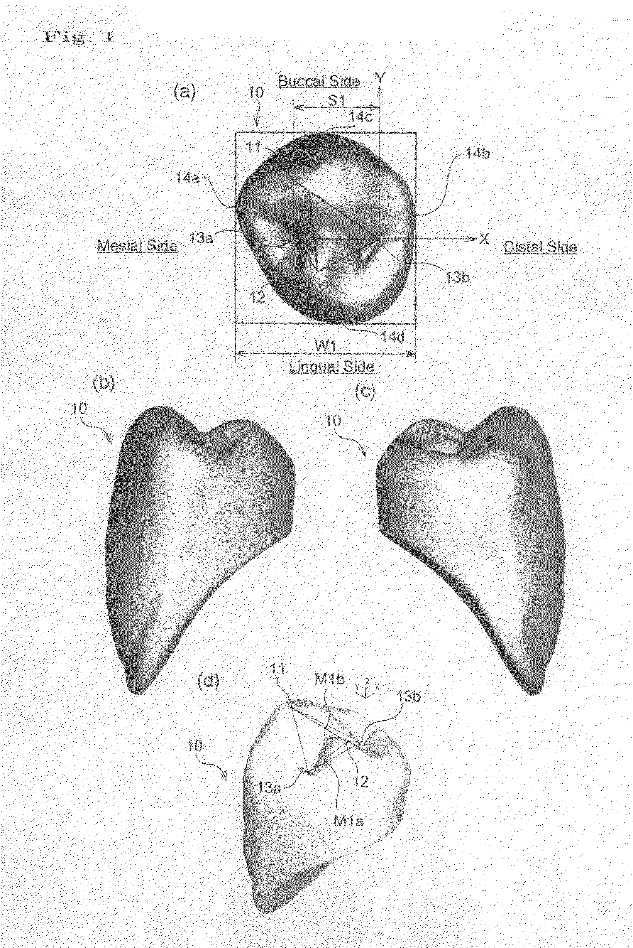
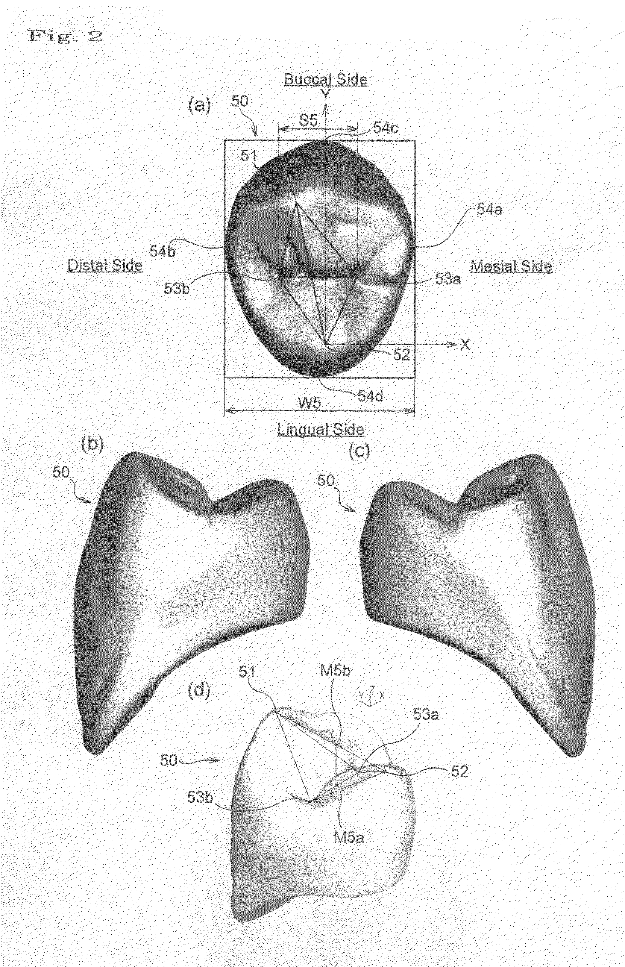
[0138]Before describing an embodiment of the present invention, names of anatomical features commonly used in both human posterior teeth and artificial posterior teeth are described.

[0139]Human posterior teeth are roughly divided into an upper section of teeth visible in appearance when a mouth is opened, and a lower section of teeth embedded in the alveolar bones. The upper section is called a dental crown, and the lower section is called a dental root. The dental crown is composed of five planes including relatively flat lateral surfaces in four directions.

[0140]With respect to the lateral directions, the side contacting with buccal mucosa is called a buccal side, and the side contacting with tongue is called a lingual side, and tooth surfaces are respectively called a buccal side surface and a lingual side surface. The side contacting with an adjacent tooth is called a proximal surface, and the side closer to the anterior tooth is called a mesial side, and the remoter side is cal...


PUM


Abstract

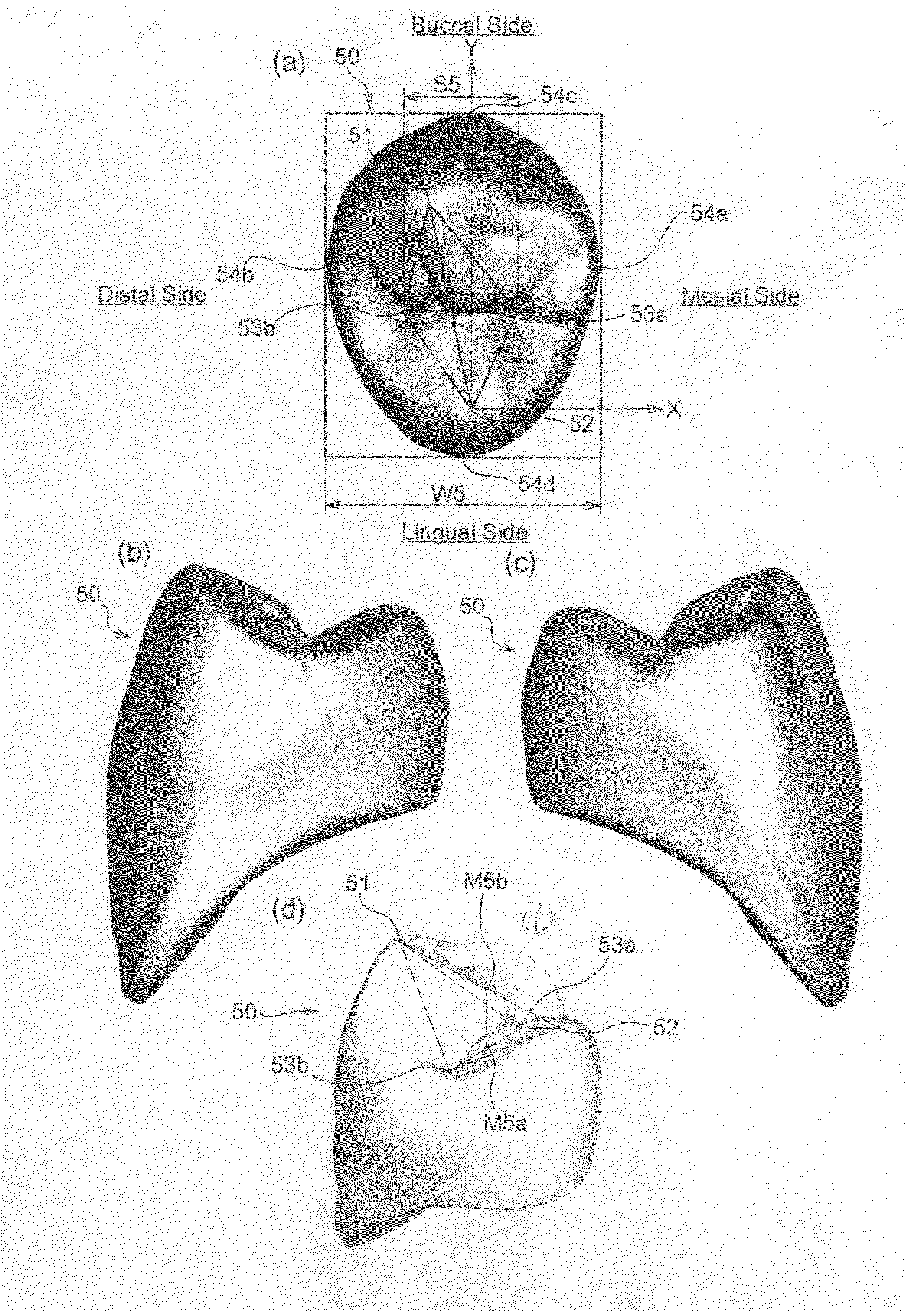
The present invention provides artificial teeth of upper and lower jaws pairing between the cusp tips and pits, allowing to operate the arrangement easily by clarifying the three-dimensional positional relation of cusp tips and pits to contact with each other in occlusion and the contact region. In an artificial tooth of a mandibular first premolar tooth having a buccal cusp tip, a lingual cusp tip, a mesial pit, and a distal pit, the azimuth originating from the distal pit, the ratio of distance to the mesial surface, distal surface, buccal surface, and the lingual surface, and the positional relation of the cusp tips and pits are set appropriately. Further, in an artificial tooth of a maxillary first premolar tooth having a buccal cusp tip, a lingual cuts point, a mesial pit, and a distal pit, the azimuth originating from the lingual cusp tip, the ratio of distance to the mesial surface, distal surface, buccal surface, and the lingual surface, and the positional relation of the cusp tips and pits are set appropriately. The distal pit of the artificial tooth of the mandibular first premolar tooth is made to contact with the lingual cusp tip of the artificial tooth of the maxillary first premolar tooth, and the buccal cusp tip of the artificial tooth of the mandibular first premolar tooth is made to contact with the mesial pit of the artificial tooth of the maxillary first premolar tooth.

Description

TECHNICAL FIELD[0001]The present invention relates to an artificial tooth preliminarily processed for use in manufacture of a plate denture.BACKGROUND ART[0002]An artificial tooth is a dental crown material preliminarily provided to a dentist or a dental technician in an anatomical form of a human tooth for use in manufacture of a plate denture. The artificial tooth is available in several types of shape, size and color, and is selected appropriately to be used depending on the condition of defect of the patient and the treatment plan.[0003]A general fabricating method of a plate denture and a method of using the artificial tooth are briefly described below.[0004]First, a model is fabricated by pouring plaster into a model of the oral shape of a patient which is taken by using an impression material such as silicone, agar or arginic acid.[0005]The manufactured plaster model is installed in a device called an articulator having hinges similar to the temporomandibular joint of the pat...

Claims


Application Information

Patent Timeline
IPC IPC(8): A61C13/08
CPCA61C13/097A61C5/08A61C5/70A61C13/08
Inventor SATOH, HIROKAZUNEGORO, NORIYUKIFUJII, KUNIHIRO
Owner SHOFU INC
Learn More