Spatially distributed ventilation boundary using electrohydrodynamic fluid accelerators
What is Al technical title?
Al technical title is built by PatSnap Al team. It summarizes the technical point description of the patent document.
a fluid accelerator and electrohydrodynamic technology, applied in the field of thermal management, can solve the problems of impracticality of conventional fan or blower ventilation, and achieve the effects of facilitating compelling product design, reducing volume and mass, and being thinner and lighter
Inactive Publication Date: 2010-05-13
TESSERA INC
View PDF12 Cites 15 Cited by
Summary
Abstract
Description
Claims
Application Information
AI Technical Summary
This helps you quickly interpret patents by identifying the three key elements:
Problems solved by technology
Method used
Benefits of technology
[0009]EHD devices may be employed to motivate flow of air in a thermal management system, such as employed to exhaust heat dissipated by integrated circuits in computing devices and electronics. For example, in devices such as laptop computers, compact scale, flexible form factor and absence of moving parts can provide design and user advantages over conventional forced air cooling technologies that rely exclusively on fans or blowers. EHD device solutions can operate silently (or at least comparatively so) with reduced volume and mass. In some cases, products incorporating EHD device solutions may be thinner and lighter than those employing conventional forced air cooling technologies. Flexible form factors of EHD devices can facilitate compelling product designs and, in some cases, may provide functional benefits.
Problems solved by technology
In some cases, spatial distributions of the ventilation boundary facilitate or enable enclosure geometries for which conventional fan or blower ventilation would be impractical.
Method used
Image
Click on the blue label to locate the original text in one second.
Reading with bidirectional positioning of images and text.
Examples
Embodiment Construction
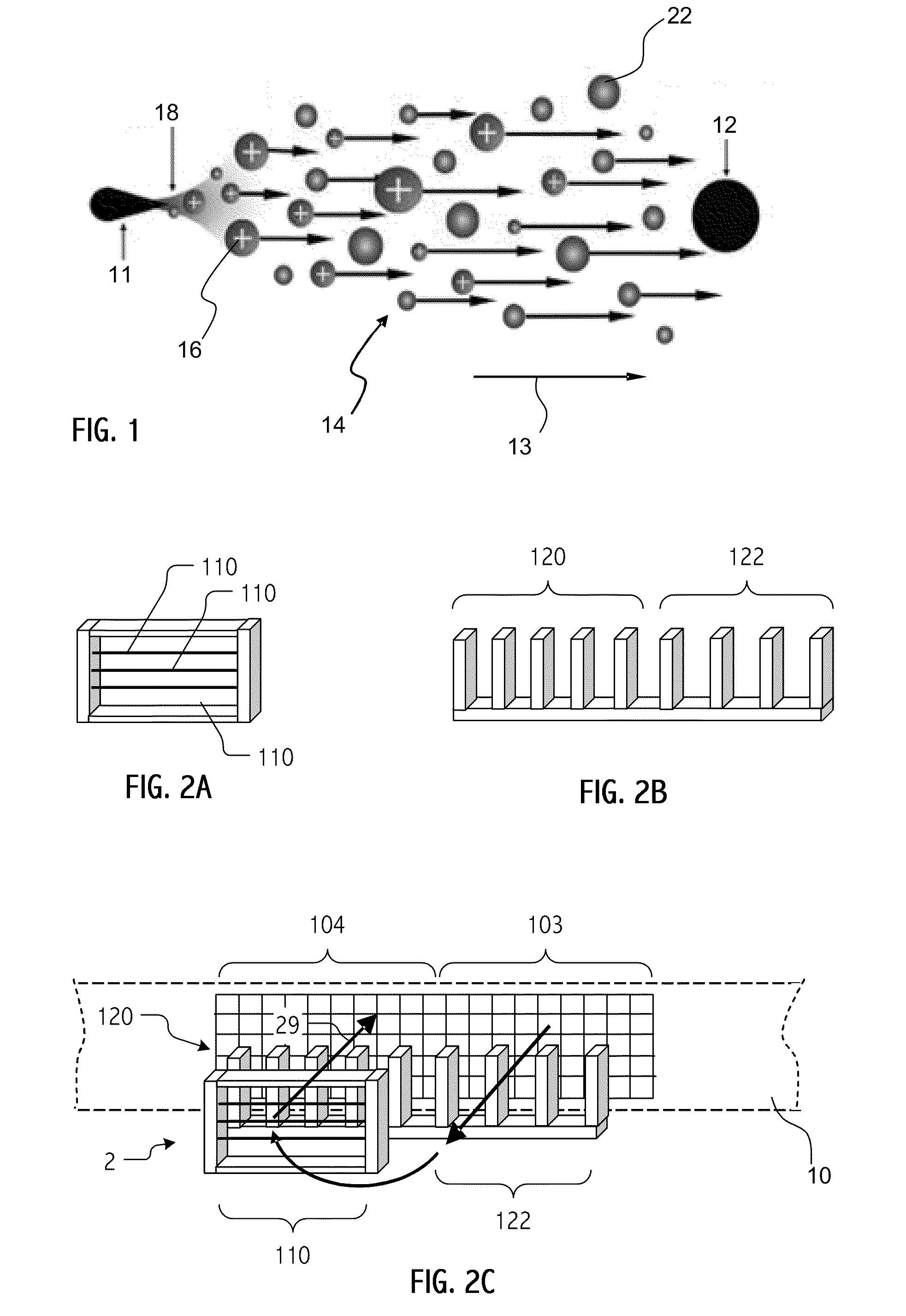
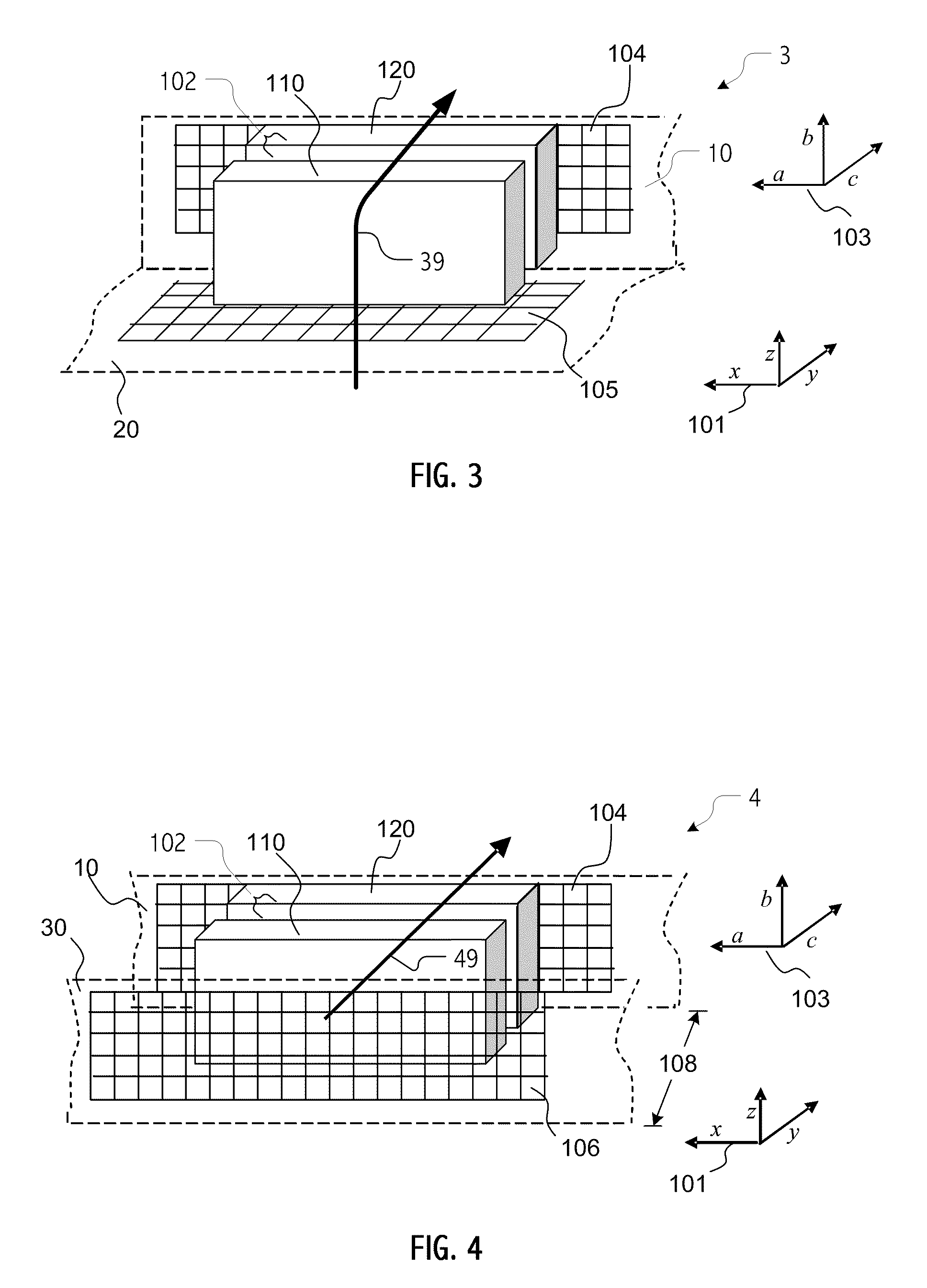
[0043]Thermal management systems described herein employ EHD devices to motivate flow of air between ventilated boundary portions of an enclosure. In this way, heat dissipated by electronics (e.g., microprocessors, graphics units, etc.) and other components may be transferred to the air flow and exhausted. Typically, the thermal management system includes heat transfer paths (often implemented as heat pipes or using other technologies) to transfer heat from where it is dissipated (or generated) to a location (or locations) within the enclosure where air flow motivated by an EHD device (or devices) flows over heat transfer surfaces.
[0044]As described herein relative to certain illustrative embodiments, some heat transfer surfaces may act as collector electrodes and participate in EHD acceleration of fluid flow (typically air flow), while additional heat transfer surfaces are provided that do not substantially contribute to motivation of fluid flow. Those heat transfer surfaces that a...
PUM
Abstract
In thermal management systems that employ EHD devices to motivate flow of air through an enclosure, spatial distribution of a ventilation boundary may facilitate reductions in flow resistance by reducing average transit distance for cooling air from an inlet portion of the ventilation boundary to an outlet portion. Some thermal management systems described herein distribute a ventilation boundary over opposing surfaces, adjacent surfaces or even a single surface of an enclosure while providing a short, “U” shaped, “L” shaped or generally straight through flow path. In some cases, spatial distributions of the ventilation boundary facilitate or enable enclosure geometries for which conventional fan or blower ventilation would be impractical. In some cases, provision of multiple portions of the ventilation boundary may allow the thermal management system to tolerate blockage or occlusion of a subset of the inlet and/or outlet portions and, when at least some of such portions are non-contiguous spatially-distributed, tolerance to a single cause of blockage or occlusion is enhanced.
Description
CROSS-REFERENCE TO RELATED APPLICATION(S)[0001]The present application claims the benefit of U.S. Provisional Application No. 61 / 113,225, filed Nov. 10, 2008. The present application is also related to commonly-owned, co-pending U.S. patent application Ser. No. ______, entitled “ELECTROHYDRODYNAMIC FLUID ACCELERATOR WITH HEAT TRANSFER SURFACES OPERABLE AS COLLECTOR ELECTRODE,” naming Jewell-Larsen, Honer, Schwiebert, Ran, Savalia and Zhang as inventors, and to commonly-owned, co-pending U.S. patent application Ser. No. ______, entitled “REVERSIBLE FLOW ELECTROHYDRODYNAMIC FLUID ACCELERATOR,” naming Jewell-Larsen, Honer, Schwiebert, Ran, Savalia and Zhang as inventors, each filed on even date herewith.BACKGROUND[0002]1. Field[0003]The present application relates to thermal management, and more particularly, to micro-scale cooling devices that use electrohydrodynamic (EHD, also known as electro-fluid-dynamic, EFD) technology to generate ions and electrical fields to control the moveme...
Claims
Application Information
Patent Timeline
Application Date:The date an application was filed.
Publication Date:The date a patent or application was officially published.
First Publication Date:The earliest publication date of a patent with the same application number.
Issue Date:Publication date of the patent grant document.
PCT Entry Date:The Entry date of PCT National Phase.
Estimated Expiry Date:The statutory expiry date of a patent right according to the Patent Law, and it is the longest term of protection that the patent right can achieve without the termination of the patent right due to other reasons(Term extension factor has been taken into account ).
Invalid Date:Actual expiry date is based on effective date or publication date of legal transaction data of invalid patent.
Patent Type & Authority Applications(United States)
IPC IPC(8): F24H9/02H02K44/02F28D15/00
CPCF04B19/006G06F1/203H02N11/006F28F2250/08
Inventor JEWELL-LARSEN, NELSHONER, KENNETH A.SCHWIEBERT, MATTRAN, HONGYUSAVALIA, PIYUSHZHANG, YAN