
Information distribution system and method, terminal apparatus, server apparatus, data reception method, and data transmission method

a technology of information distribution system and server apparatus, which is applied in the direction of data switching networks, instruments, frequency-division multiplexes, etc., can solve the problems of insufficient improvement of the efficiency of utilization of communication facilities and inefficient use of communication facilities, and achieve the effect of efficient utilization of communication facilities

Inactive Publication Date: 2010-05-06
SONY CORP
View PDF18 Cites 11 Cited by
  • Summary
  • Abstract
  • Description
  • Claims
  • Application Information

AI Technical Summary

Benefits of technology

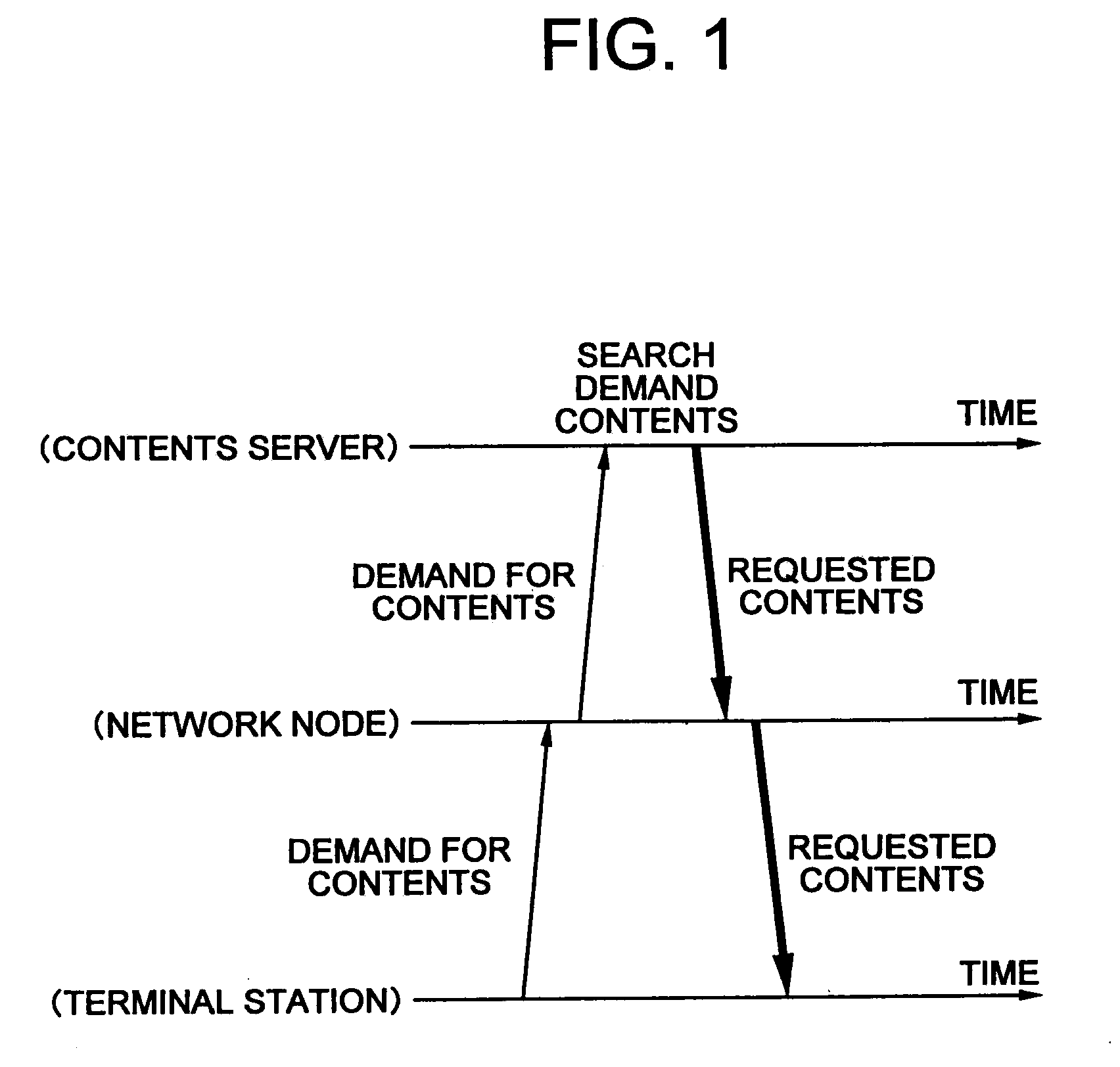
The present invention provides an information distribution system and method that can efficiently distribute information over time and utilize communication facilities effectively. The system includes a server apparatus and a terminal apparatus. The server apparatus receives a request for information from the terminal apparatus and schedules a point of time for distribution based on the state of the communication line. The terminal apparatus generates a request signal for the desired information and sends it to the server apparatus. The server apparatus distributes the information to the terminal apparatus at the scheduled point of time. This system and method can help to even out traffic loads and make efficient use of communication facilities.

Problems solved by technology

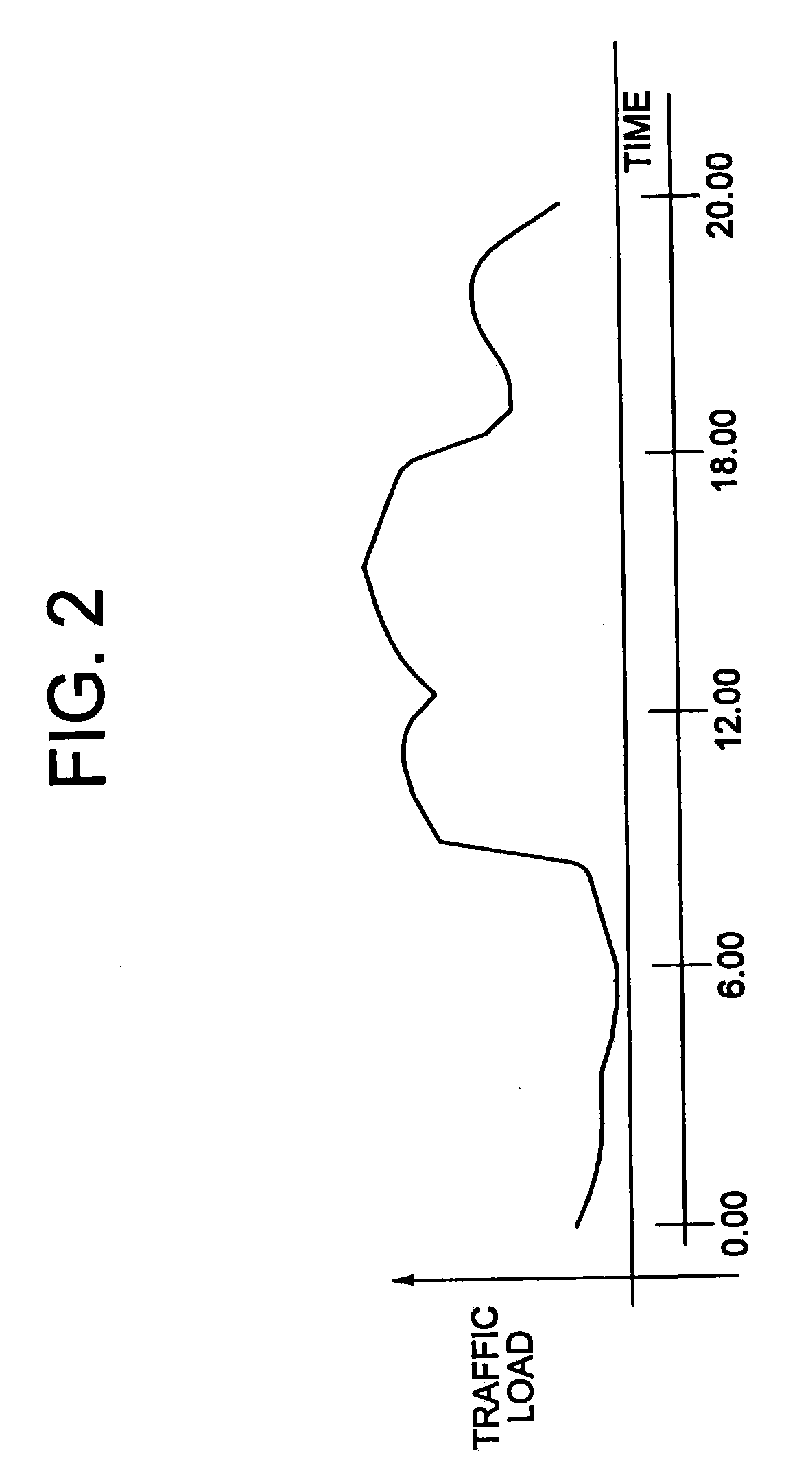
Accordingly, it suffers from the disadvantage that communication facilities are not in use during the night time and other time bands when the communication traffic is low, so the communication facilities are not efficiently used.
Further, it suffers from the disadvantage of the difficulty in sufficient improvement of the efficiency of utilization of the communication facilities because a network operator often determines a traffic load of a communication system in order to provide an acceptable quality of service during the time bands when the traffic load is large.

Method used


Image

  • Information distribution system and method, terminal apparatus, server apparatus, data reception method, and data transmission method
  • Information distribution system and method, terminal apparatus, server apparatus, data reception method, and data transmission method
  • Information distribution system and method, terminal apparatus, server apparatus, data reception method, and data transmission method

Examples


first embodiment

[0024]An embodiment of the present invention will be explained with reference to FIGS. 3 to 7.

[0025]In the present embodiment, the present invention will be explained by giving as an example a cellular wireless communication system.

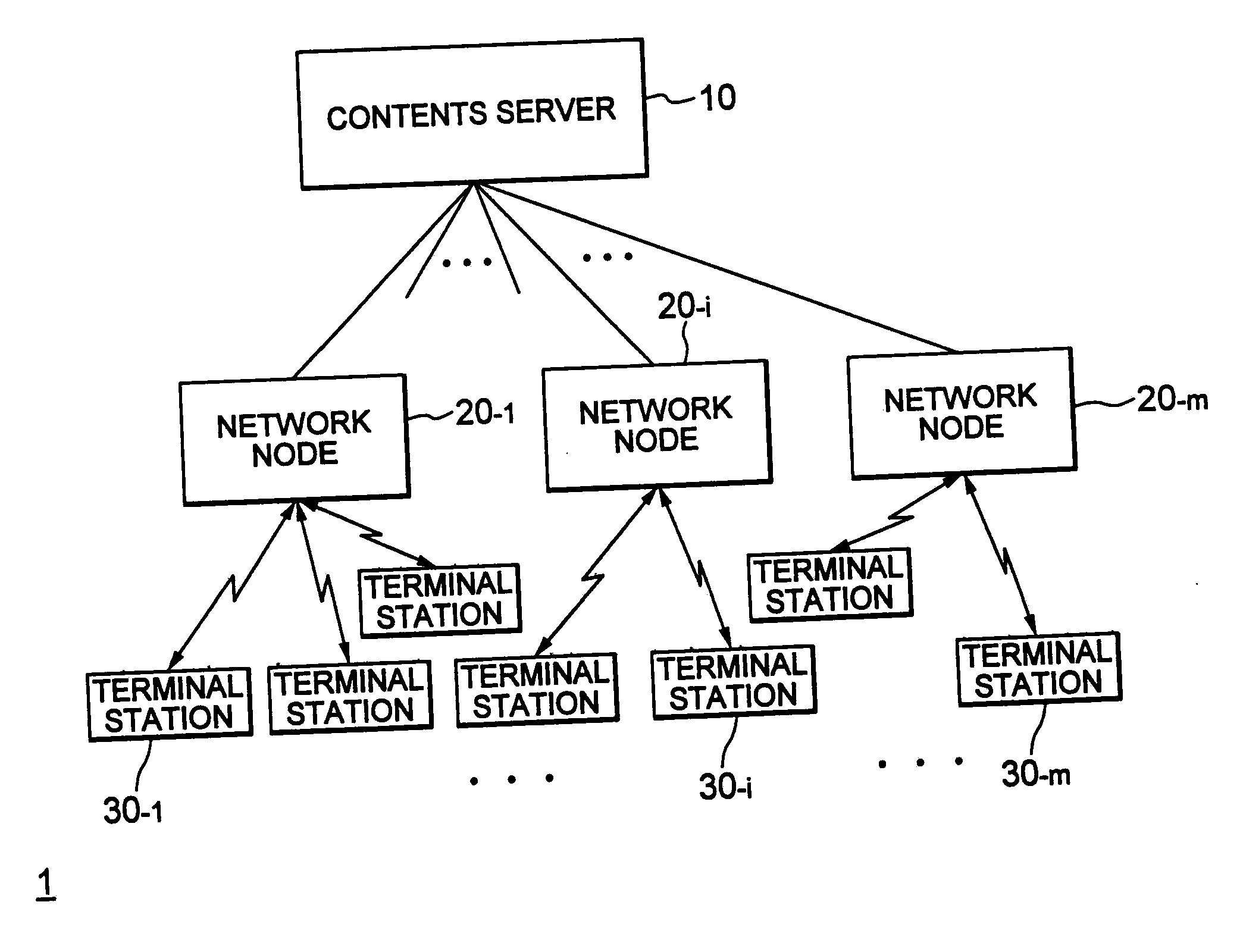
[0026]First, the network configuration of a cellular wireless communication system of the present embodiment will be explained with reference to FIG. 3.

[0027]FIG. 3 is a view of the network configuration of the cellular wireless communication system of the present embodiment.

[0028]A cellular wireless communication system 1 of the present embodiment has the configuration of arranging in layers as shown in the figures a contents server 10, a plurality of network nodes 20−1 to 20−n, and a plurality of terminal stations 30−1 to 30−m. Information is transmitted from the contents server 10 to the respective terminal stations 30−j (j=1 to m) via the network nodes 20−i (i=1 to n).

[0029]In the cellular wireless communication system 1, the network nodes 20−1 to 20−...

second embodiment

[0075]Several modes of information distribution will be explained next.

[0076]First, a mode where the contents server 10 notifies the terminal servers 30−j in advance of the time band for transfer of information contents as explained above will be explained.

[0077]In this case, the ACK signal sent from the contents server 10 to a terminal server 30−j for a demand for information distribution includes information of the time band during which the contents server 10 will transmit the information contents to the terminal station 30−j demanding distribution.

[0078]The contents server 10 which received the demand for information distribution from the terminal station 30−j calculates the time band estimated to have less communications traffic during the time until the informed deadline based on results of operations up to then and the transmission schedule of the information contents received until then. Then, it includes the information of the scheduled point of time of distribution determi...

third embodiment

[0088]Next, a mode of receiving information contents by a user designating a time band and region will be explained.

[0089]First, the contents server 10 or the network node 20−i averages and calculates the traffic load in the past for different regions in advance. For example, it sets the relay area of a network node 20−i as a calculated region. Alternatively, it sets an area comprised by relay areas of several network nodes 20−i as the calculated region. Then, the contents server 10 or the network node 20−i suitably predicts a traffic load by region and by time band based on the schedule of distributing the information contents scheduled until then and calculation of the traffic load and, based on this prediction, calculates communication fees for the respective regions / time bands.

[0090]The communication fees for each region / time band are broadcasted to the terminal stations 30−1 to 30−m using a BCCH (broadcast control channel) for simultaneous broadcast of control signals from a ba...


PUM


Abstract

An information distribution system and method capable of averaging a traffic load over time and effectively utilizing communication facilities, wherein a terminal station 30 transmits to a contents server 10 a distribution request for desired information including information of time limit of distribution, and the contents server 10 receives the distribution request, estimates a time band where the traffic load is small in the communications system in the period until the time limit of distribution, pages the terminal station again at that period of time, and, if the terminal station is in a state able to receive the information content, transmits the requested information content to the terminal station 30 through a network node.

Description

[0001]This is a Divisional of application Ser. No. 09 / 647,964, filed on Jan. 8, 2001, which is currently pending. application Ser. No. 09 / 647,964 is the U.S. National Stage of International Application No. PCT / JP00 / 00705, filed on Feb. 9, 2000, and claims priority to Japanese Patent Application No. 11-032065, filed Feb. 9, 1999. The entire contents of these applications are incorporated herein by reference.TECHNICAL FIELD[0002]The present invention relates to an information distribution system and method, a terminal apparatus, a server apparatus, a data reception method, and a data transmission method able to be applied to a network system such as a cellular wireless communication system and particularly capable of averaging a traffic load over time and efficiently utilizing a communication infrastructure.BACKGROUND ART[0003]As an example of a general communication system for distributing information in the related art, web browsing over the Internet can be mentioned.[0004]A communi...

Claims


Application Information

Patent Timeline
Patent Type & Authority Applications(United States)
IPC IPC(8): G06F15/16H04L12/14H04L12/28H04L29/08
CPCH04L12/14H04L12/1485H04W28/0289H04L67/322H04L67/325H04L69/329H04L67/61H04L67/62
Inventor SAKODA, KAZUYUKISUZUKI, MITSUHIRO
Owner SONY CORP
Learn More