
Hybrid battery system for implantable cardiac therapy device

Inactive Publication Date: 2010-05-06
PACESETTER INC
View PDF8 Cites 16 Cited by
  • Summary
  • Abstract
  • Description
  • Claims
  • Application Information

AI Technical Summary

Benefits of technology

[0014]The present system and method employs a hybrid battery comprised of at least two types of cells to power an implantable cardiac therapy device (ICTD). A first type of cell provides low voltage but high energy density. The first type of cell directly provides power to the ICTD for purposes of routine cardiac monitoring, pacing, and general low current ICTD operations (including, for example, communications). The first type of cell is also coupled to a second cell via a simple DC-to-DC converter. The second type of cell is maintained at full or nearly full charge by the energy provided by the first type of cell. The second type of cell has low internal resistance and high voltage, making it suitable to rapidly charge ICTD capacitors for cardiac shocking (that is, for defibrillation). The second type of cell also has other properties optimizing it for usage in an ICTD.

Problems solved by technology

However, ICTDs have additional, specialized power requirements due to the specific nature of their function.
Defibrillation therapy, however, requires rapid, high voltage, high current delivery to the heart.
Further, the LiSVO battery has a high energy density (which, in theory, provides long battery life), and its self-discharge rate is low.
However, the LiSVO battery suffers from disadvantages as well.
In some cases, the time to charge the shocking capacitors could be doubled, which may render the battery unacceptable for defibrillation.
This may result in a medical decision to replace the device, which in turn means the patient may have to accept a premature surgery.
In the past, the increased battery charge time has been a major issue for ICTDs.
However, the second cell typically has lower energy density that the first battery.
However, existing hybrid batteries may still not be optimally tuned for application in an ICTD.
For example, the voltage output or output current of the second cell may not be as high as desirable.
The second cell may also have undesirable properties associated with recharging (for example, it may not be safe to charge the second cell too quickly), requiring complex regulation circuitry.
In addition, full advantage may not be taken of the electrical properties of the primary cell.
Furthermore, existing hybrid batteries may not have an optimized energy density distribution (that is, an optimized distribution of storage capacity) between the primary and secondary cells.
Finally, the secondary cell may introduce an undesirable degree of bulk or weight in the design of the ICTD.

Method used


Image

  • Hybrid battery system for implantable cardiac therapy device
  • Hybrid battery system for implantable cardiac therapy device
  • Hybrid battery system for implantable cardiac therapy device

Examples


Embodiment Construction

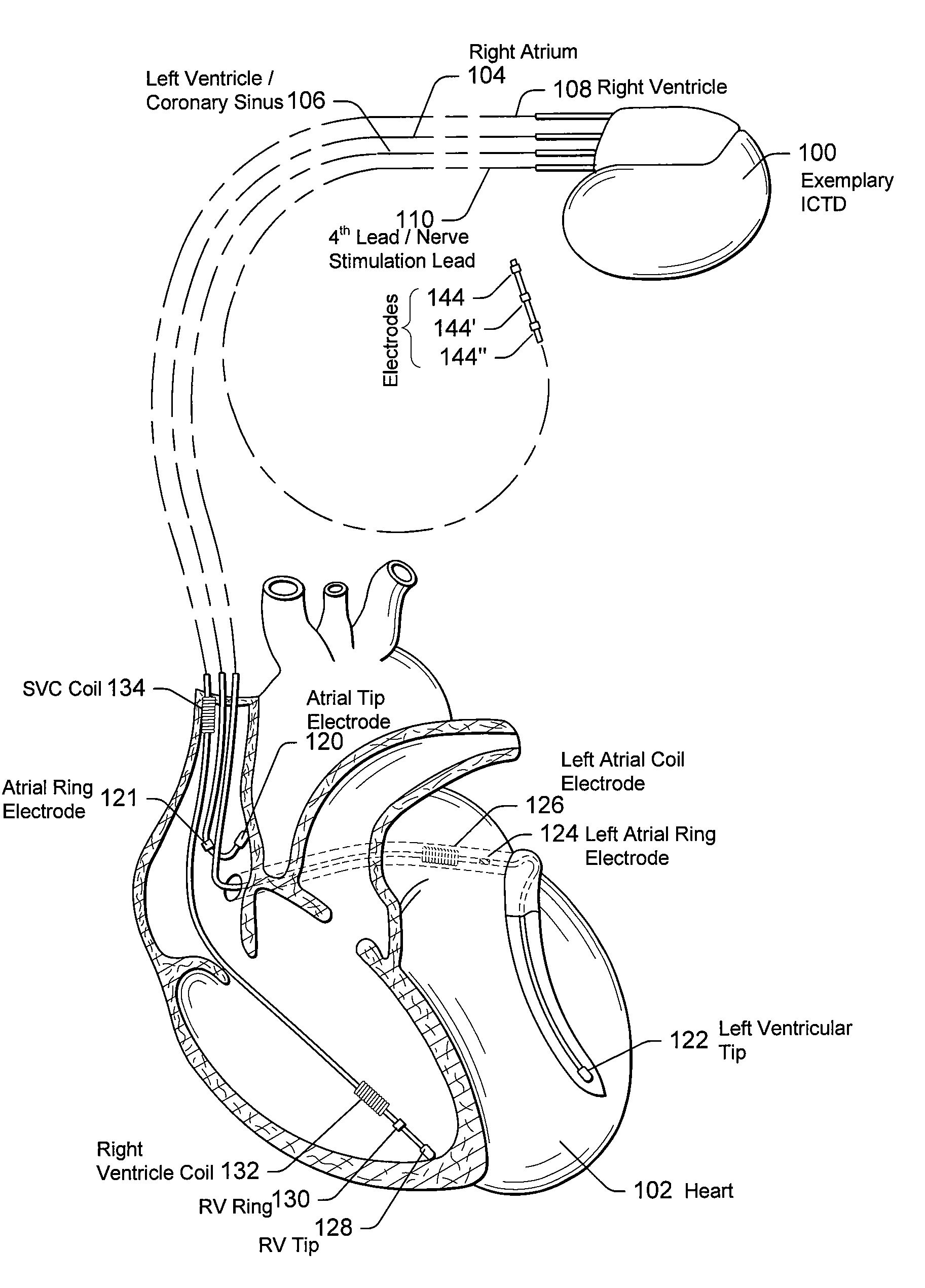
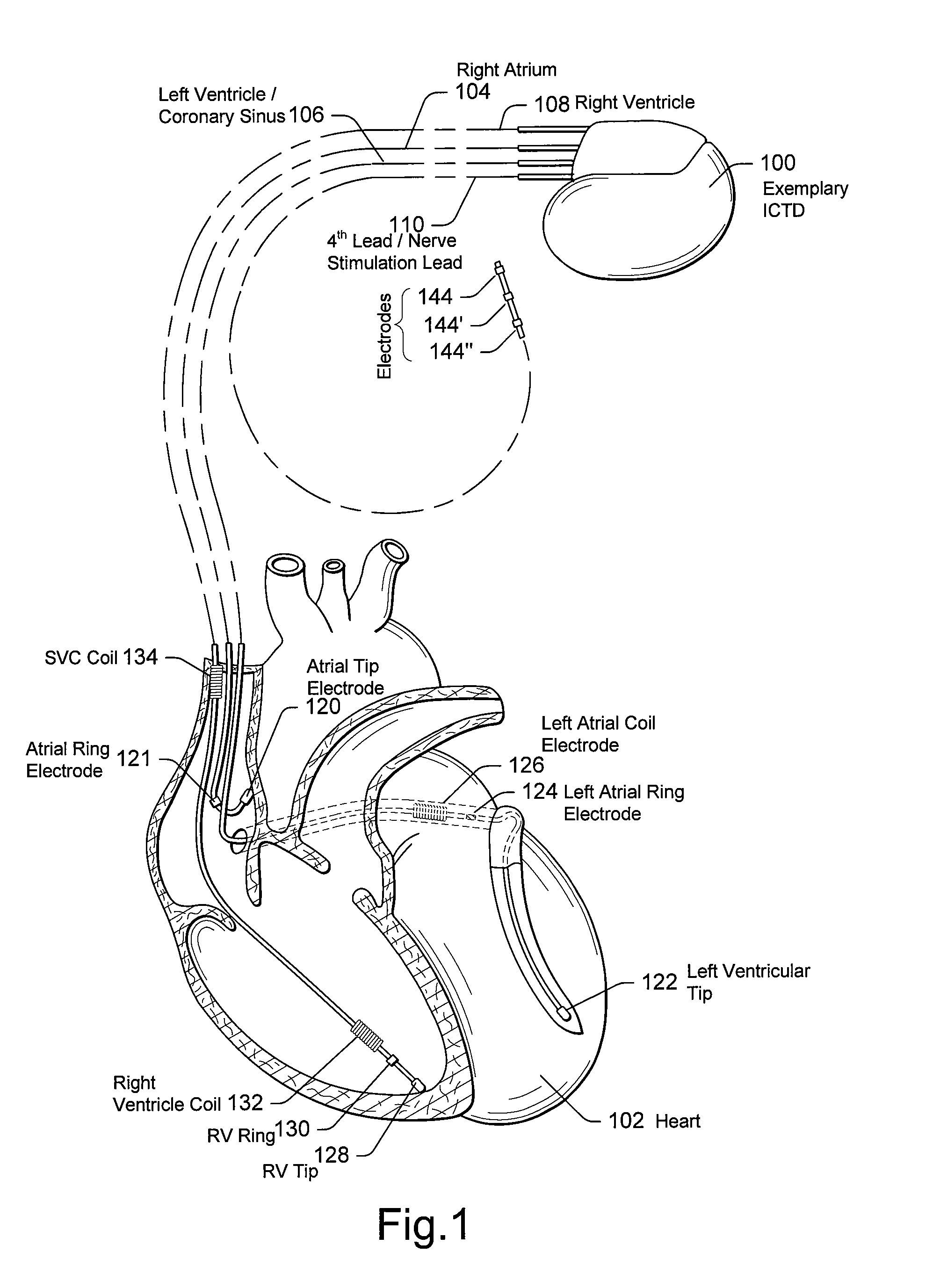
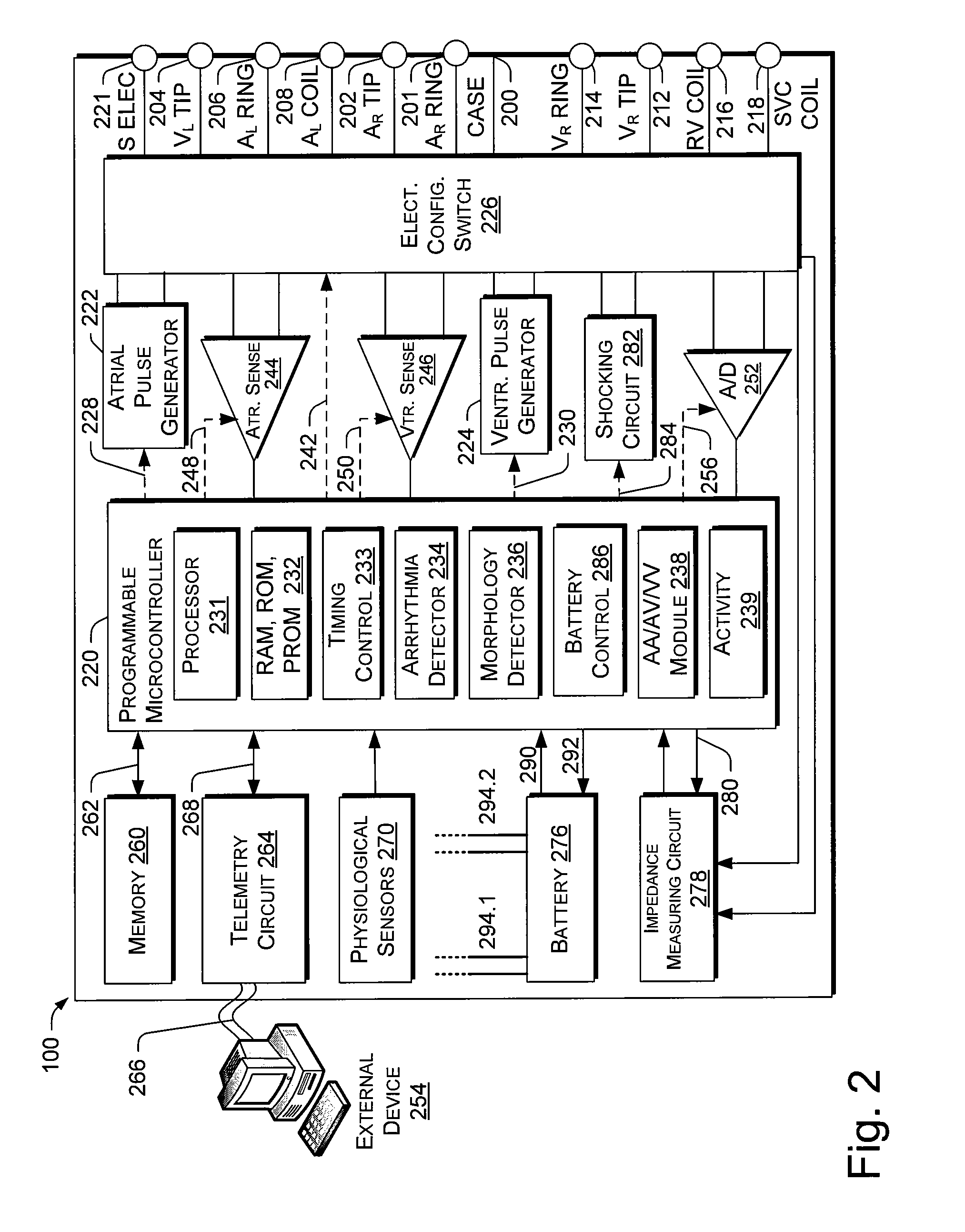
[0029]1. Overview[0030]2. Exemplary Environment—Overview[0031]3. Exemplary ICTD in Electrical Communication with a Patient's Heart[0032]4. Functional Elements of an Exemplary ICTD[0033]5. ICTD Programmer[0034]6. System and Method For Hybrid Battery Optimized for ICTD[0035]7. Choice of Power Cells[0036]8. Lithium Ion Polymer Cell vs. Lithium / Silver Vanadium Oxide Cell[0037]9. Lithium Ion Polymer Cell vs. Standard Lithium Ion Cell[0038]10. Charging of Lithium Ion Polymer Cell from Primary Cell[0039]11. Relative Storage Capacities of Different Types of Cells[0040]12. Alternative Embodiments[0041]13. Conclusion

1. Overview

[0042]The following detailed description of systems and methods for a hybrid battery optimized for an implantable cardiac therapy device refers to the accompanying drawings that illustrate exemplary embodiments consistent with these systems and methods. Other embodiments are possible, and modifications may be made to the embodiments within the spirit and scope of the me...


PUM


Abstract

A system and method for powering an implantable cardiac therapy device (ICTD) uses a hybrid battery system. In an embodiment, the hybrid battery system includes of a first type of power cell and a second type of power cell. The first power cell is configured to power low voltage, low current background operations of the ICTD. The second power cell is configured to power high voltage, high current cardiac shocking. The second power cell is further configured to be charged by the first power cell via a continuous, non-regulated charging process, thereby reducing the complexity of the charging circuitry. The system is further configured so that when cardiac shocking is in progress, only the secondary power cell powers the shocking capacitor(s) of the ICTD, and the first power cell is electrically isolated from the shocking capacitor(s). This configuration contributes to longer battery life of the hybrid battery system.

Description

RELATED APPLICATIONS[0001]This application is related to co-pending and commonly-owned U.S. patent applicaton Ser. No. ______, filed on even date herewith, entitled “Hybrid Battery System With Bioelectric Cell For Implantable Cardiac Therapy Device”, (attorney docket number A07E3046 [1587.1870000]), which is incorporated by reference herein in its entirety as if reproduced in full below.BACKGROUND[0002]1. Field of the Invention[0003]The present invention relates generally to implantable cardiac therapy devices, and to power sources for the same. More particularly, the invention relates to a hybrid battery system for use in an implantable cardiac therapy device.[0004]2. Background Art[0005]Implantable cardiac therapy devices (ICTDs) enjoy widespread use for providing convenient, portable, sustained therapy for cardiac patients with a variety of cardiac arrhythmias. ICTDs may combine a pacemaker and defibrillator in a single implantable device. Such devices may be configured to provid...

Claims


Application Information

Patent Timeline
IPC IPC(8): A61N1/00H02J7/00
CPCA61N1/378A61N1/3956A61N1/3981H01M6/16H01M6/5033H01M10/0525H01M10/425H01M10/44H01M16/00H02J7/0054H02J7/342Y02E60/10H02J2310/23
Inventor JIANG, NAIXIONGBORNZIN, GENE A.BEAUVAIS, JOSEPH
Owner PACESETTER INC
Learn More